Method and device for simulating slip on vehicle test benches

a vehicle and test bench technology, applied in vehicle tyre testing, instruments, force/torque/work measurement, etc., can solve the problems of inability to precisely set the coefficient of friction, the frictional force limit the maximum tractive force of the wheel, and the inability to provide approximations for the further development of the affected vehicle safety system

Inactive Publication Date: 2004-01-15
RENK AG
View PDF13 Cites 20 Cited by
  • Summary
  • Abstract
  • Description
  • Claims
  • Application Information

AI Technical Summary

Problems solved by technology

However, such test journeys are dangerous for the driver and cannot be reproduced owing to the changing environmental conditions or the different performances of even the same drivers of different course paths so that these tests can only provide approximations for the further development of affected vehicle safe

Method used


Image

  • Method and device for simulating slip on vehicle test benches
  • Method and device for simulating slip on vehicle test benches
  • Method and device for simulating slip on vehicle test benches

Examples


Embodiment Construction

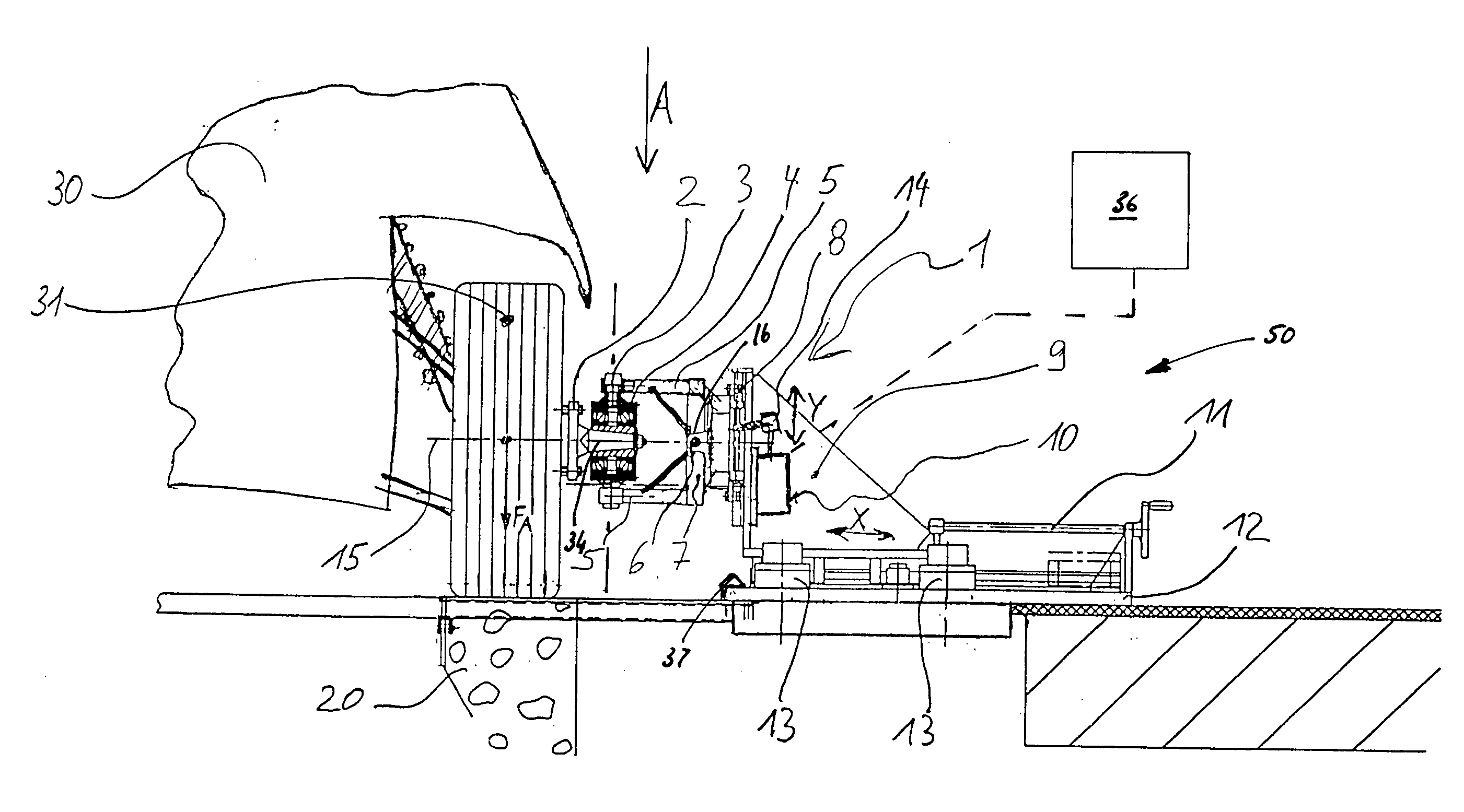
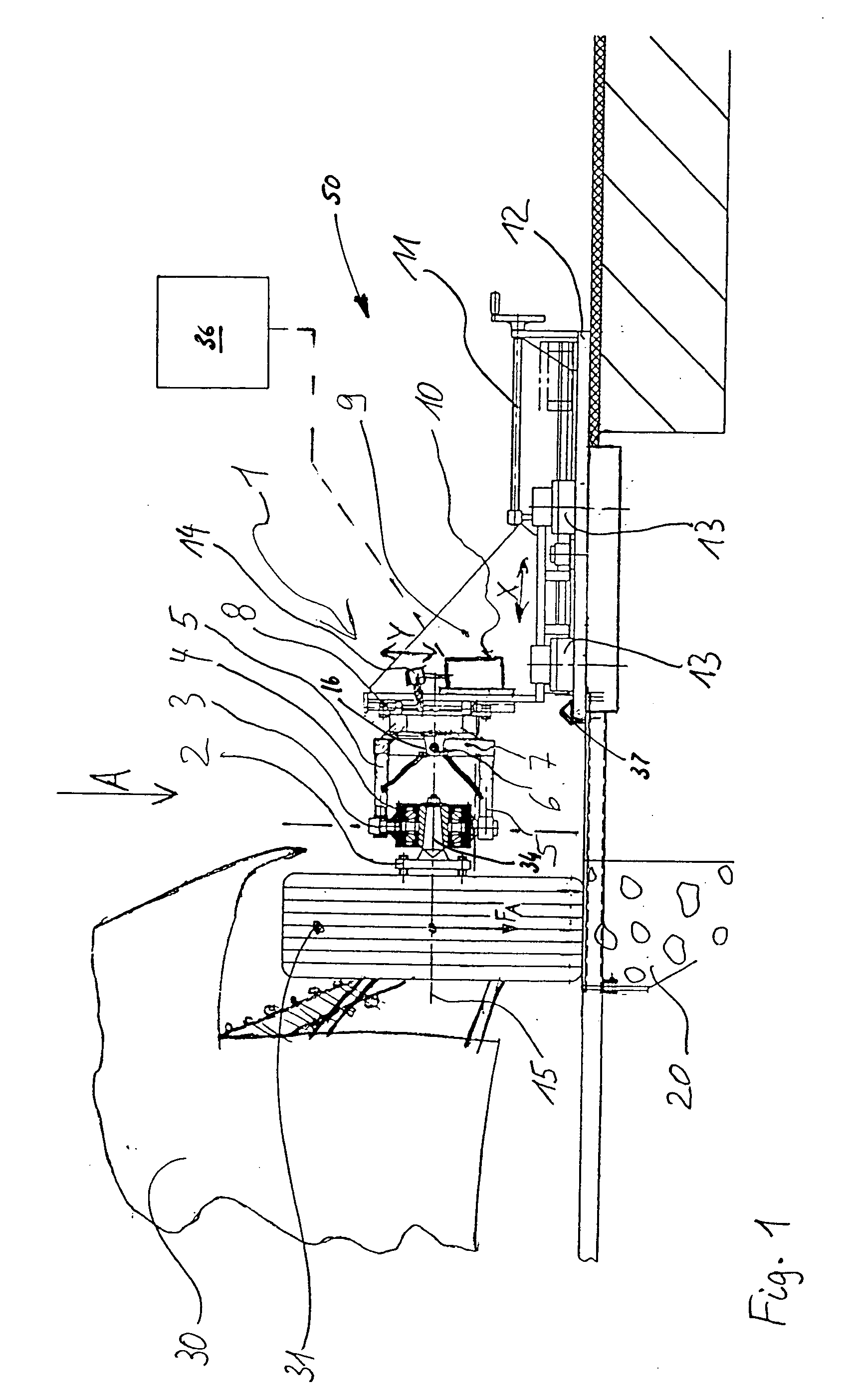
[0015] FIG. 1 shows a wheel 31 of a vehicle 30 on a test surface, such as a test roller 20, i.e. test device. The illustrated test roller 20 is what is referred to as a vertex-type roller in which the wheels 31 roll approximately in the vertex region of the roller 20. However, other testing surfaces, for example flat belts, are also conceivable. The term test roller also includes all other conceivable testing surfaces as disclosed herein in the following description. The test roller 20 is preferably arranged in a pit underneath the vehicle 30 and can drive or brake the wheel 31 which includes a tire. For this purpose, a test bench controller can be provided, which can set, through actuation, different wheel loads corresponding to driving, braking, etc. on a test roller 20 in order to simulate various driving states such as acceleration, uphill travel, deceleration of the vehicle 30. The test bench 50 is preferably a standard version such as is usually provided for testing vehicles. ...


PUM


Abstract

A device for simulating slip on vehicle test benches wherein a vehicle wheel which rolls on a movable testing surface of a test device such as a test roller or flat belt and performs the object of changing the frictional force between the wheel and the testing surface without necessarily having to change the coefficient of friction, A lifting/lowering device changes the contact force FA of the wheel in a predeterminable way from the tire to an apparatus as the wheel rotates.

Description

[0001] 1. Field of the Invention[0002] The present invention relates to a method and a device for simulating slip on vehicle test benches in accordance with the equation F.sub.R=F.sub.A.times.the coefficient of friction C of a vehicle wheel rolling on a test device such as a test roller or flat belt.[0003] 2. Description of the Related Art[0004] In order to test antilock brake systems (ABS) on brakes, traction controllers on drive systems or electronic stability programs for preventing skidding, it is generally known to drive the respectively equipped vehicles over test routes. For this purpose there are slalom courses, circular courses, or oblique planes which can have various underlying surface coverings in different locations and the coefficient of friction can be partially reduced by water when necessary. It is thus possible, for example, to create different frictional conditions on the two sides of a vehicle and to generate slip between the tire and underlying surface on a driv...

Claims


Application Information

Patent Timeline
IPC IPC(8): G01L5/28G01M17/007G01M17/02
CPCG01L5/282G01M17/022G01M17/0074G01M17/0072
Inventor KARRER, MATHIASMUND, ANDREAS
Owner RENK AG
Why Eureka
Try Eureka