
Method for measuring the rotation speed of a vehicle wheel

a technology of vehicle wheels and rotation speed, which is applied in the direction of instruments, braking systems, devices using electric/magnetic means, etc., can solve the problems of affecting the measurement speed of the vehicle wheel, affecting the measurement of the period of the measurement signal, and the measurement of the voltage threshold is particularly complex to define, so as to facilitate the determination of the rotation speed of the wheel

Active Publication Date: 2017-03-02
SAFRAN LANDING SYSTEMS
View PDF13 Cites 8 Cited by
  • Summary
  • Abstract
  • Description
  • Claims
  • Application Information

AI Technical Summary

Benefits of technology

The patent is about using the Fourier transform to make it easier to identify and measure the rotation speed of a wheel, even when the wheel is rotating slowly. This is useful because the noise in the measurement is spread out over the spectral domain, making it easier to identify the useful line.

Problems solved by technology

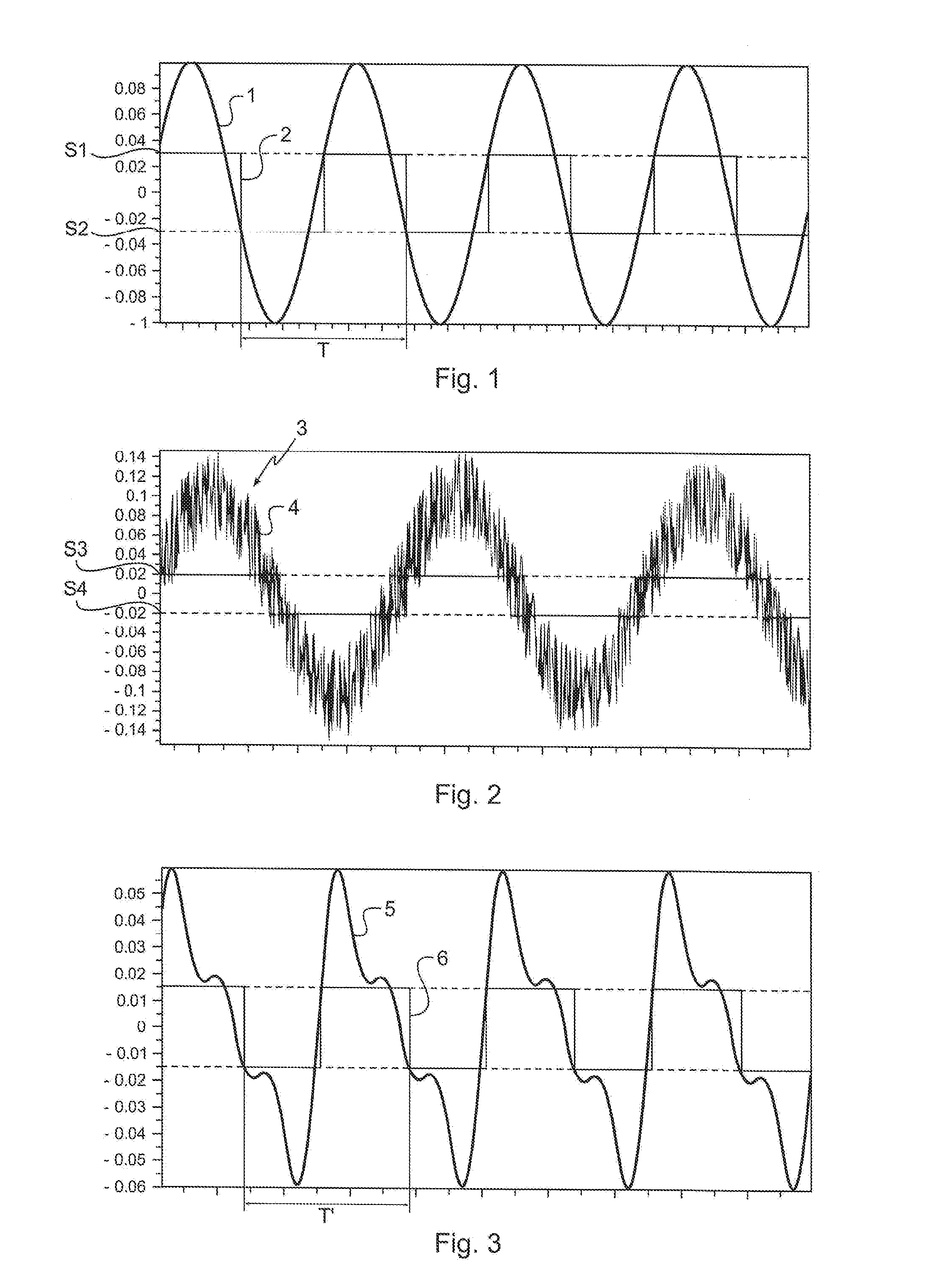
However, decreasing the threshold voltage makes the measurement much more sensitive to parasitic noise resulting from various perturbations undergone by the tachometer, the electronic module or the cable: electrical perturbations (noise of the components), electromagnetic perturbations (motors and other electrical equipment) and mechanical perturbations (repercussion of the vibrations and shocks undergone by the wheel during the measurement carried out by the tachometer).
Thus, if a threshold of 0 volts were used, even the slightest parasitic noise present in the measurement signal would corrupt the measurement of the period of the measurement signal.
The voltage thresholds are therefore particularly complex to define since they affect not only the low-frequency measurement performance of the tachometer, but also the robustness to measurement noise.
It is however impossible to filter the low-frequency noise resulting from perturbations of mechanical origin (for example generated by mechanical resonances at a few tens or hundreds of hertz), because their frequencies correspond to the useful frequency band of the measurement signal.

Method used


Image

  • Method for measuring the rotation speed of a vehicle wheel
  • Method for measuring the rotation speed of a vehicle wheel
  • Method for measuring the rotation speed of a vehicle wheel

Examples


Embodiment Construction

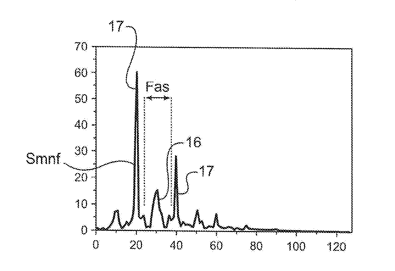
[0031]The method of the invention is here implemented to measure the rotation speed of a wheel of an aircraft.

[0032]The aircraft wheel is equipped with a magnetic tachometer that is connected, via a cable run over a landing-gear leg bearing the wheel, to an electronic measurement module integrated into a remote computer located in a hold of the aircraft. The method of the invention is here implemented by the electronic measurement module.

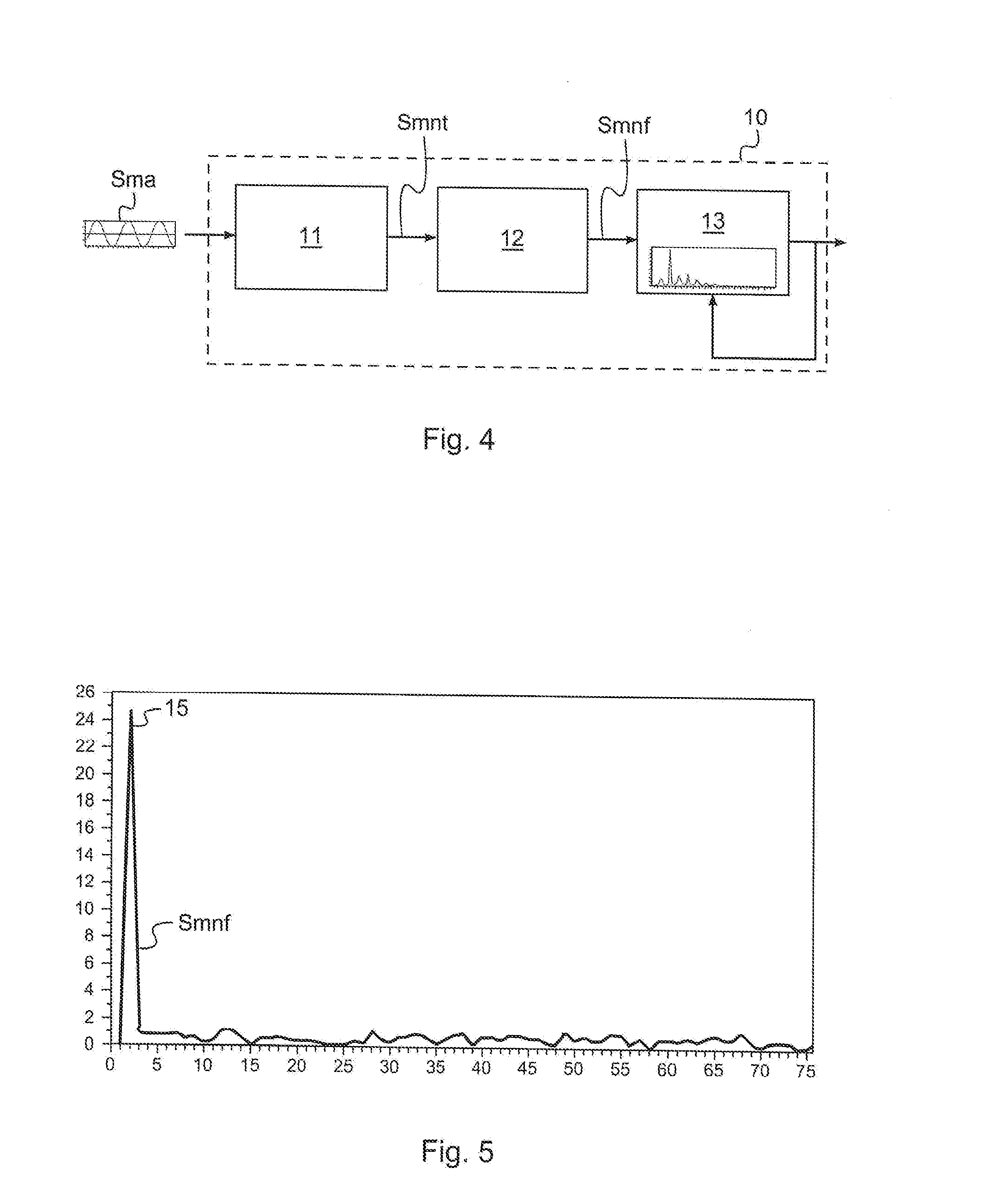
[0033]With reference to FIG. 4, the electronic measurement module 10 includes an analogue-digital converter 11, a computational module 12 and a frequency-analysing module 13.

[0034]The tachometer generates, when the wheel turns, an analogue measurement signal Sma. The analogue measurement signal Sma contains a useful signal the frequency of which is representative of the rotation speed of the wheel, and undesirable noise resulting from perturbations of electrical, electromagnetic or mechanical origin to which the tachometer, the cable and the electro...


PUM


Abstract

A method for measuring the rotation speed of a wheel including the steps of: acquiring an analogue measurement signal (Sma) generated by a magnetic tachometer and containing a useful signal the frequency of which is representative of the rotation speed of the wheel; digitizing in real-time the analogue measurement signal (Sma) in order to obtain a time-dependent digital measurement signal (Smnt); calculating a Fourier transform of the time-dependent digital measurement signal (Smnt) in order to obtain a frequency-dependent digital measurement signal (Smnf); and carrying out a frequency analysis in order to identify by a search for peaks a useful spectral line (16) so as to obtain the frequency of the useful signal and therefore the rotation speed of the wheel.

Description

[0001]The invention relates to the measurement of the rotation speed of a vehicle wheel.BACKGROUND OF THE INVENTION[0002]The tachometers generally used to measure the rotation speed of aircraft wheels are magnetic analogue tachometers (also called inductive analogue tachometers).[0003]Such a tachometer conventionally includes a rotating portion securely fastened to the wheel and equipped with magnets or toothed elements made from a ferromagnetic material, and a fixed portion comprising a magnetic sensor (coil of conductive wire, Hall-effect sensor, etc.) delivering a periodic measurement signal generated by a magnetic-field variation resulting from the rotation of the wheel.[0004]The frequency and / or amplitude of this measurement signal are proportional to the rotation speed of the wheel.[0005]The measurement signal is acquired by an electronic measurement module connected by a cable to the tachometer.[0006]When the frequency of the measurement signal is used to obtain the rotation ...

Claims


Application Information

Patent Timeline
IPC IPC(8): G01P3/487G01R23/16G01D5/244G06F17/15G01P3/48G01D5/14
CPCG01P3/487G01P3/48G01R23/16G01D5/24409G06F17/156G01D5/145B60T8/171G01P21/02
Inventor ZABULON, JOELFRANK, DAVIDFALLET, GUILLAUME
Owner SAFRAN LANDING SYSTEMS
Learn More