Connector

a technology of connecting rods and connectors, applied in the direction of coupling device connections, coupling protective earth/shielding arrangements, non-rotary current collectors, etc., can solve the problems of connecting rods, vibration, noise generation,

Active Publication Date: 2008-10-23
TOYOTA JIDOSHA KK
View PDF12 Cites 9 Cited by
  • Summary
  • Abstract
  • Description
  • Claims
  • Application Information

AI Technical Summary

Benefits of technology

[0008]An object of the present invention is to provide a connector having sound generated from the connector caused by vibration reduced.

Problems solved by technology

Particularly in the case where the connector is employed for a wiring harness to which vibration of the vehicle is applied, there is a possibility of the connector, if of a general type, being detached by vibration.
Vibration of a large connector in response to vibration of the motor can cause generation of noise.

Method used


Image

  • Connector
  • Connector
  • Connector

Examples


Embodiment Construction

[0028]An embodiment of the present invention will be described in detail with reference to the drawings. In the drawings, the same or corresponding components have the same reference characters allotted, and description thereof will not be repeated.

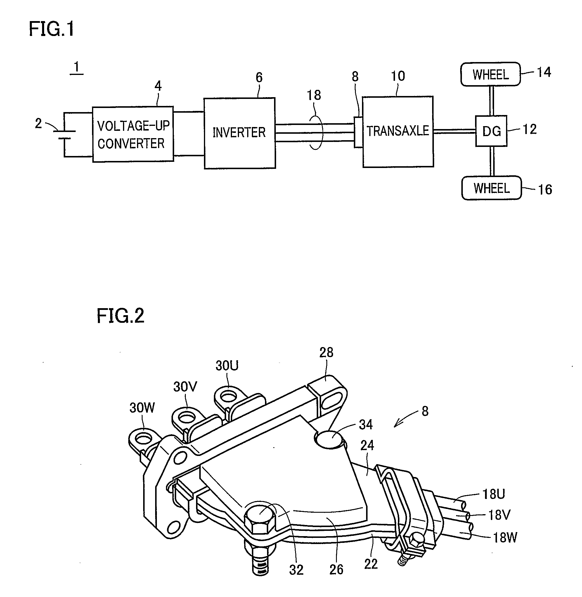
[0029]The vehicle shown in FIG. 1 in which the connector of the present invention is applied may be, for example, an electric car, a hybrid vehicle, a fuel cell electric vehicle, and the like.

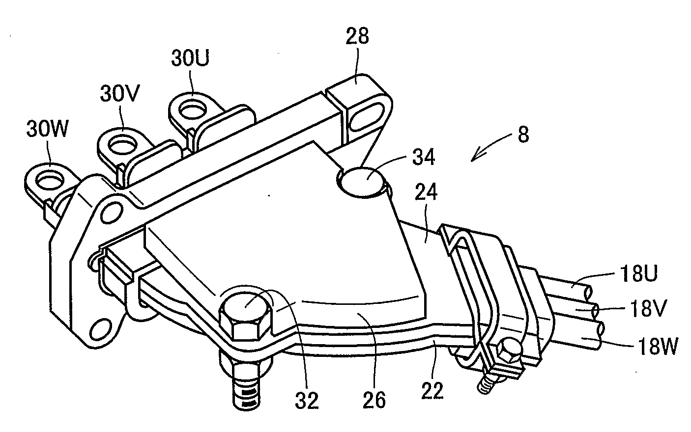
[0030]Referring to FIG. 1, the vehicle includes a direct current power supply 2, a voltage-up-converter 4 boosting the voltage output from direct current power supply 2, an inverter 6 converting the direct current voltage boosted by voltage-up-converter 4 into a 3-phase alternating current, a transaxle 10 incorporating a motor driven by inverter 6, a differential gear 12 connected to the output shaft of transaxle 10, and wheels 14 and 16 driven by differential gear 12.

[0031]Connection is established between inverter 6 and transaxle 10 by a 3-phase po...


PUM


Abstract

A connector includes a main body supporting a power cable, and a sound-proof member attached by a bolt to the top surface of the main body identified as the sound emitting surface to absorb sound emitted from the main body due to vibration. The main body includes a base provided with bulges in which three power cables are accommodated, respectively, and a lid over the base with power cables accommodated. The sound-proof member is effective as long as it is attached to the side face of the lid where it is expected to readily emit noise, i.e., on one side. The sound proof member can be also attached to the side face of the base. A connector having sound generated from the connector caused by vibration reduced is provided.

Description

TECHNICAL FIELD[0001]The present invention relates to connectors, particularly a connector employed in a connecting portion to which vibration is applied.BACKGROUND ART[0002]A connector is a component employed for connecting electric wiring. Particularly in the case where the connector is employed for a wiring harness to which vibration of the vehicle is applied, there is a possibility of the connector, if of a general type, being detached by vibration.[0003]Japanese Patent Laying-Open No. 2001-176602 discloses the technology of improving adhesion between a connector and a vibration isolation cover to ensure the vibration isolation capability by incorporating a rubber member between the connector employed in a vehicle and the vibration isolation cover.[0004]In recent years, attention has been directed to electric cars, fuel cell electric vehicles and hybrid vehicles in consideration of the high fuel cost and environmental grounds. Such vehicles are mounted with motors for driving wh...

Claims


Application Information

Patent Timeline
Patent Type & Authority Applications(United States)
IPC IPC(8): H01R13/533
CPCH01R13/533
Inventor MIZUTANI, TATSUHIKOOTAGAKI, AKIRA
Owner TOYOTA JIDOSHA KK
Why Eureka
Try Eureka