Locking apparatus

a technology of locking apparatus and locking rod, which is applied in the direction of keyhole guards, securing communication, program control, etc., can solve the problems of troublesome handling of the related art, unreliable durability, and no ease of use of the related ar

Inactive Publication Date: 2004-01-22
UNIREC +1
View PDF3 Cites 12 Cited by
  • Summary
  • Abstract
  • Description
  • Claims
  • Application Information

AI Technical Summary

Benefits of technology

[0016] The fingerprint reader is contained in the chamber, which is opened and closed with the lid. The lid is interlocked with the switch of the power supply circuit, so that the power supply circuit is turned on and off in response to the opening and closing of the lid. Namely, no switching operation is asked for when a person unlocks the door, thereby improving the operability of the apparatus.
[0017] The power supply circuit is turned on and off by opening and closing the lid without pressing the fingerprint reader with a finger. This improves the durability of the fingerprint reader.
[0018] The power supply circuit can be turned off without the use of, for example, a timer. This helps reduce the cost of the locking apparatus.
[0020] In addition to the effects of the first and second aspects, the third aspect forms the chamber in a shape to receive a finger through the opening, orients the fingerprint reader in the chamber toward a finger inserting direction, and supports the lid so that the lid may open when pushed into the chamber. To make the fingerprint reader read a fingerprint, a person pushes the lid with a finger and inserts the finger into the chamber. Then, the fingerprint reader reads the fingerprint. This improves the operability of the apparatus.
[0021] The third aspect employs the pusher to push the lid toward the position where the lid closes the opening of the chamber. When the person removes the finger from the chamber, the lid automatically returns to the position to close the opening of the chamber and turn off the power supply circuit. This surely reduces the power consumption of the locking apparatus and elongates the service life of a battery when the power supply circuit is powered by the battery.

Problems solved by technology

This apparatus of the related art involves troublesome handling.
In this way, the related art provides no ease of use.
The fingerprint reader 107 must every time be pressed with a finger to turn on the power switch, and therefore, the reader 107 has a risk of breakage and is unreliable in durability.
This increases the cost of the apparatus.
This surely reduces the power consumption of the locking apparatus and elongates the service life of a battery when the power supply circuit is powered by the battery.

Method used


Image

  • Locking apparatus
  • Locking apparatus
  • Locking apparatus

Examples


Embodiment Construction

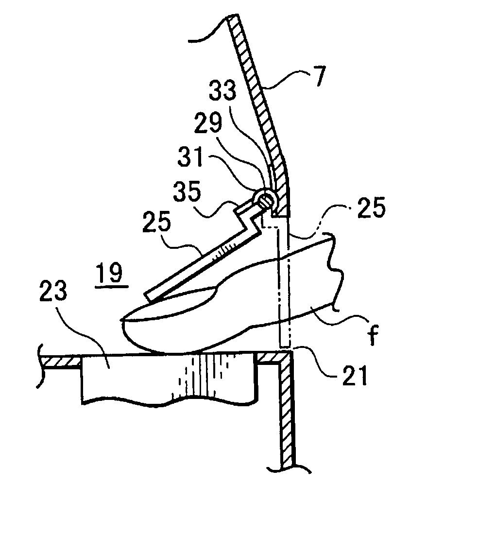
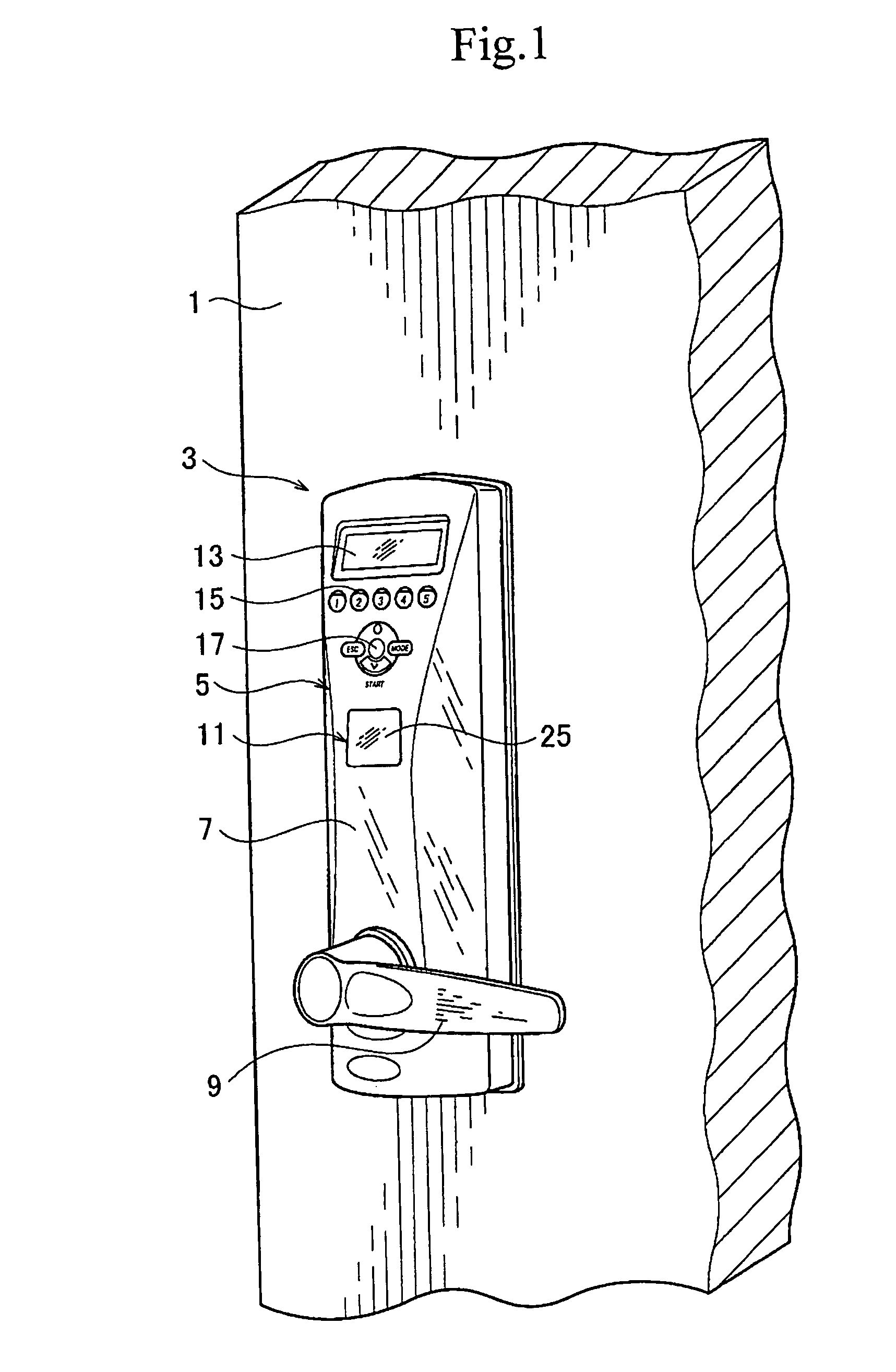
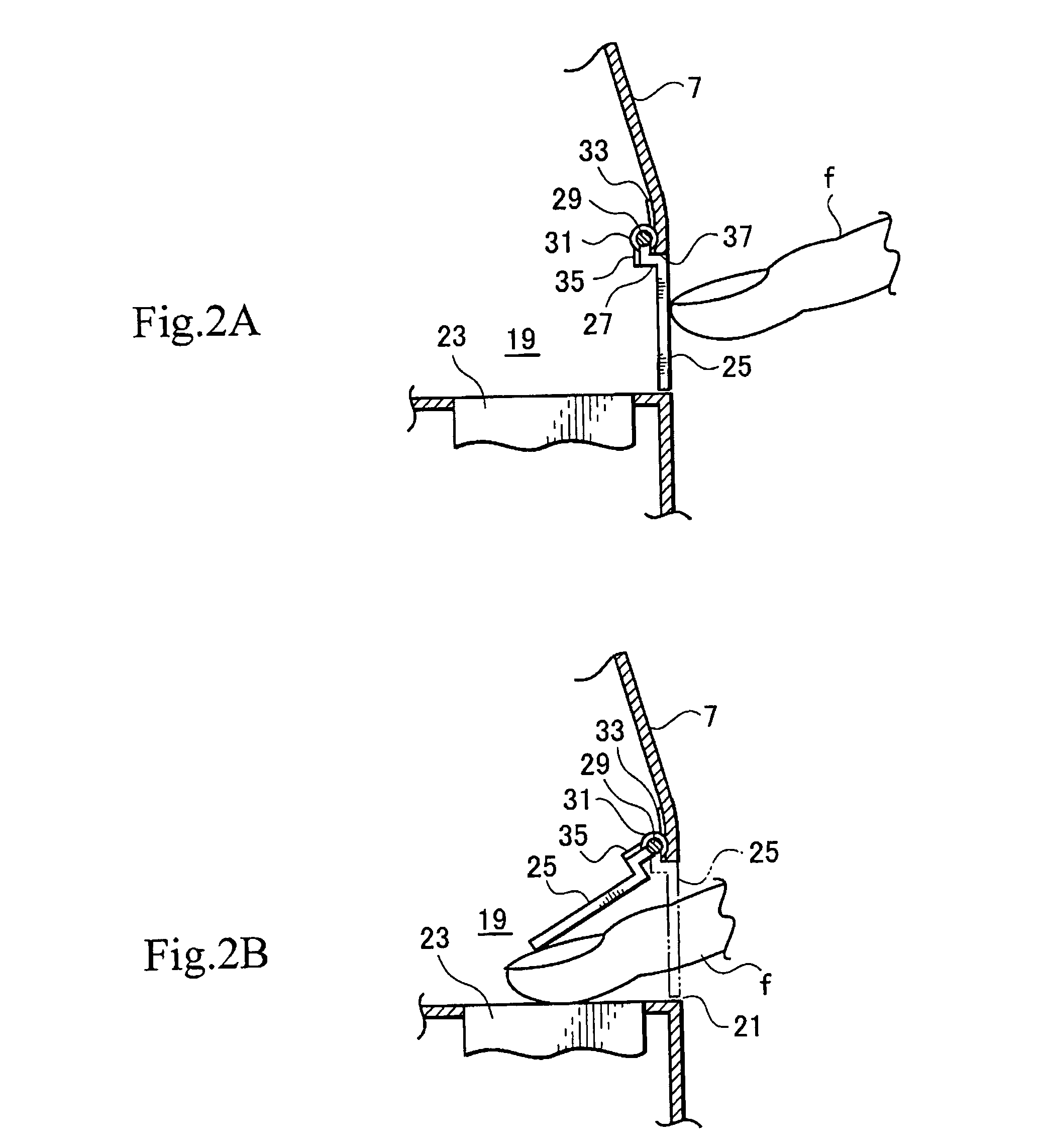
[0031] FIG. 1 is a perspective view partly showing a door 1 with a locking apparatus 3 according to an embodiment of the present invention. The locking apparatus 3 has an exterior unit 5, a fingerprint reader 23, and a fingerprint verifier 11. The fingerprint reader 23 reads a fingerprint of a person, the fingerprint verifier 11 verifies the read fingerprint based on registered fingerprint data, and if the person is authenticated through the fingerprint verification, the locking apparatus 3 unlocks the door 1 locked with the locking apparatus 3.

[0032] The exterior unit 5 has a housing 7 fixed to the door 1 and a lever 9 supported by the housing 7. The lever 9 is used to open the door 1. The housing 7 houses the fingerprint verifier 11, an LCD panel 13, registration buttons 15, and set buttons 17. The LCD panel 13 is used to display various functions. The registration buttons 15 are used to enter, for example, an identification number. The set buttons 17 are used to set the locking a...


PUM


Abstract

A locking apparatus has improved operability and is manufacturable at low cost. The locking apparatus has a fingerprint reader (23), a fingerprint verifier (11), and a power supply circuit. The fingerprint reader reads a fingerprint. The fingerprint verifier verifies the read fingerprint based on registered fingerprint data, and according to a result of the verification, authenticates a person who entered the fingerprint. If the person is authenticated, the locking apparatus unlocks a door locked with the locking apparatus. The locking apparatus comprises a chamber (19) configured to contain the fingerprint reader, a lid (25) configured to open and close the opening of the chamber, and a switch (41) provided for the power supply circuit and configured to interlock with the lid so as to turn on and off the power supply circuit in response to the opening and closing of the lid.

Description

[0001] 1. Field of the Invention[0002] The present invention relates to a locking apparatus capable of verifying a fingerprint and unlocking a door locked with the locking apparatus.[0003] 2. Description of Related Art[0004] An example of a locking apparatus is disclosed in Japanese Unexamined Patent Application No. 2002-70382 briefly shown in FIGS. 8 and 9. FIG. 8 is a front view partly showing a door 101 seen from the outside thereof and FIG. 9 is an enlarged perspective view showing an operation unit 103 installed on the door 101.[0005] The operation unit 103 of the related art has a housing 105 attached to the door 101. The housing 105 incorporates a fingerprint reader 107. The reader 107 is in a chamber 109 defined in the housing 105. The chamber 109 has an opening 111 to be opened and closed with a lid 113. Usually, the opening 111 is closed with the lid 113.[0006] The locking apparatus receives necessary power from a power source such as a battery or a DC source. The power so...

Claims


Application Information

Patent Timeline
Patent Type & Authority Applications(United States)
IPC IPC(8): E05B49/00E05B65/06G07C9/00
CPCG07C9/00166G07C9/00571G07C9/00563G07C9/38Y10T70/5832Y10T70/7068E05B49/00
Inventor YAMAGISHI, JUNICHI
Owner UNIREC
Why Eureka
Try Eureka