Check patentability & draft patents in minutes with Patsnap Eureka AI!

System and method for automatically calibrating an alignment reference source

a reference source and automatic calibration technology, applied in the field of alignment systems, can solve the problems of sensor suite components shifting or malfunctioning, manual calibration is often undetectedly time-consuming and expensive, and the field of automatic calibration is particularly problemati

Inactive Publication Date: 2004-02-12
RAYTHEON CO
View PDF3 Cites 14 Cited by
  • Summary
  • Abstract
  • Description
  • Claims
  • Application Information

AI Technical Summary

Problems solved by technology

However, manual calibration is often undesirably time-consuming and expensive.
Manual calibration in the field is particularly problematic.
Shock and vibration during missile or aircraft maneuvers may cause sensor suite components to shift or malfunction.
Conventionally, this requires that the sensor suite be shipped back to the factory, which is inefficient, expensive, and time-consuming.
Automatically determining required calibration scale factors obviates tedious manual calibration.
Consequently, certain sensors may be replaced in the field, which saves costly downtime.

Method used


Image

  • System and method for automatically calibrating an alignment reference source
  • System and method for automatically calibrating an alignment reference source
  • System and method for automatically calibrating an alignment reference source

Examples


Embodiment Construction

[0028] While the present invention is described herein with reference to illustrative embodiments for particular applications, it should be understood that the invention is not limited thereto. Those having ordinary skill in the art and access to the teachings provided herein will recognize additional modifications, applications, and embodiments within the scope thereof and additional fields in which the present invention would be of significant utility.

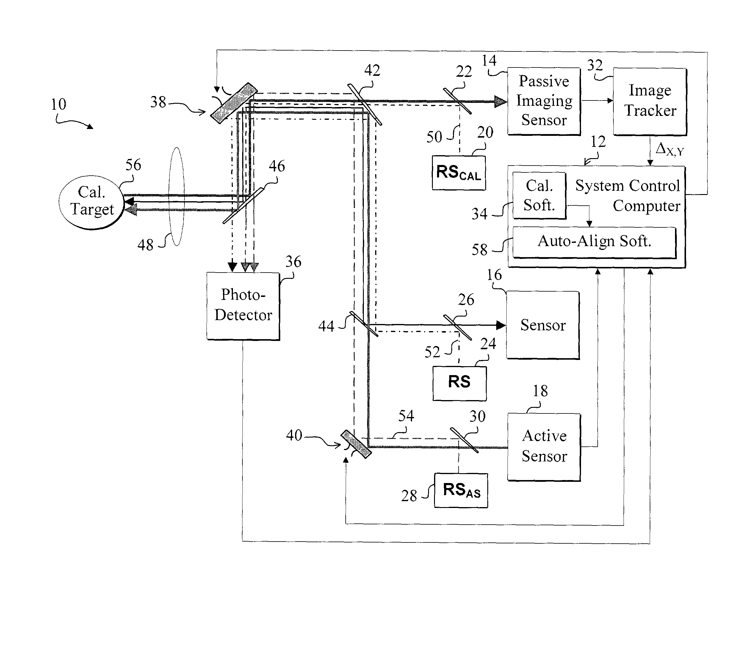
[0029] FIG. 1 is a diagram of a sensor suite 10 employing an automatic reference source calibration system, which includes a system control computer 12 (also called a system control processor), and is constructed in accordance with the teachings of the present invention. For clarity, various well-known components, such as power supplies, focusing lenses, clocking circuits, amplifiers, nonuniformity correction modules, and so on, have been omitted from the figures, however those skilled in the art with access to the present teachings ...


PUM


Abstract

A system (10, 12, 34) for calibrating an apparatus (10) for aligning components (20) relative to a desired line of sight. The system includes a first mechanism (70) for generating a command designed to move a line-of-sight of one of the components (20) to a first position, the line-of-sight moving to a second position in response thereto. A second mechanism (36, 38, 74, 78) automatically compensates for a variation between the first position and the second position via a scale factor (78). In a specific embodiment, the system (10, 12, 34) further includes a third mechanism (74) that adjusts the command via the scale factor (78) so that the second position matches the first position. The line-of-sight is coincident with a first reference beam (50). The second mechanism (36, 38, 74, 78) includes a photodetector (36) and the steering mirror (38). The steering mirror (38) is responsive to the command and positioned to direct the first reference beam (50) onto the photodetector (36) to create a reference spot corresponding to the first reference beam (50) on the surface of the photodetector (36). The second mechanism (36, 38, 74, 78) includes a computer (12) that communicates with the steering mirror (38) and receives output from the photodetector (36). The computer (12) runs software (34, 70) for generating the command and measuring the first position and the second position of the first reference beam (50) by measuring corresponding positions of the reference spot on the surface of the photodetector (36).

Description

[0001] 1. Field of Invention[0002] This invention relates to alignment systems. Specifically, the present invention relates to systems and methods for calibrating reference sources and accompanying reference source steering mechanisms in systems for aligning sensors or transmitters to desired optical paths.[0003] 2. Description of the Related Art[0004] Alignment systems are employed in various demanding applications including imaging, chemical analysis, and military targeting, surveillance, and reconnaissance systems. Such applications require alignment systems that can accurately and efficiently align components, such as optics, along a desired line-of-sight. These applications often require precise alignment of multiple constituent sensor components to ensure accurate handover of sensing function from one sensor to another or to facilitate multi-sensor data integration or fusion.[0005] Precise system component alignment is particularly important in multi-spectral electro-optical s...

Claims


Application Information

Patent Timeline
Patent Type & Authority Applications(United States)
IPC IPC(8): G01B11/27
CPCG01B11/272
Inventor MESSINA, PETER V.
Owner RAYTHEON CO
Features
  • R&D
  • Intellectual Property
  • Life Sciences
  • Materials
  • Tech Scout
  • Unparalleled Data Quality
  • Higher Quality Content
  • 60% Fewer Hallucinations
Learn More