
Herringbone gear teeth and method for manufacturing same

a technology of gear teeth and gear teeth, which is applied in the field of gear teeth, can solve the problems of limited manufacturing of herringbone gears, limited hardness of parts and tooth dimension accuracy, and scarcity of large-pitch high-accuracy sykes cutters, and achieves high accuracy

Inactive Publication Date: 2004-02-19
LUFKIN GEARS LLC
View PDF8 Cites 33 Cited by
  • Summary
  • Abstract
  • Description
  • Claims
  • Application Information

AI Technical Summary

Benefits of technology

"The invention is a method for manufacturing herringbone gears with improved hardness and tooth quality. The method involves starting with non-hardened cylindrical stock material, establishing a continuous beam across the gear, and then carburizing and finishing the gear to the high accuracy characteristic of conventional gaps. The resulting gear has improved hardness and surface characteristics, making it ideal for power transmission applications. The method also allows for the use of high accuracy machine tools and ensures smooth operation and reliable performance. The invention provides a herringbone gear with improved hardness and tooth quality, which was previously limited to carburized hardened steel of hardness less than 35 Rockwell C."

Problems solved by technology

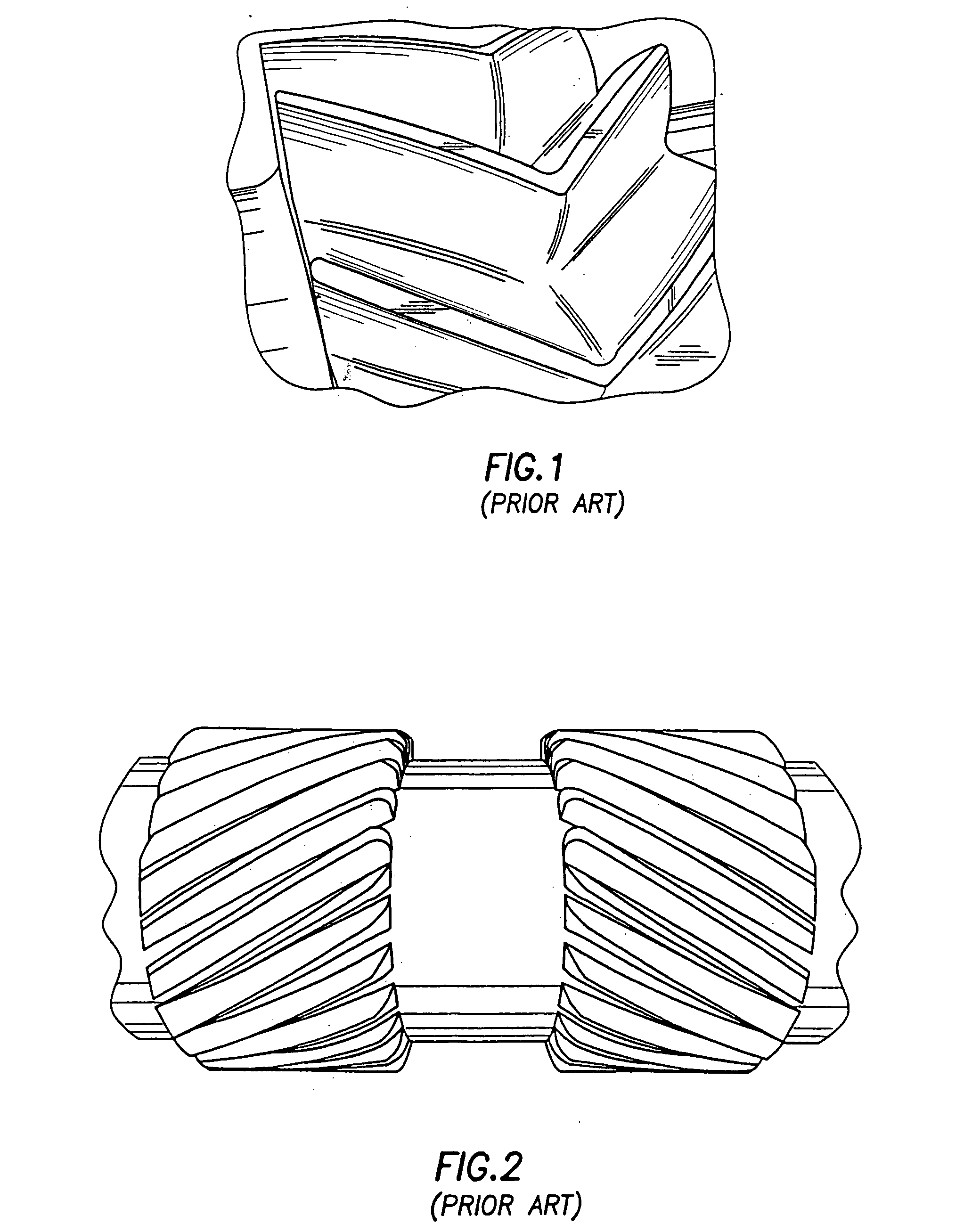
Although continuous beam double helical gearing has been in use for over fifty years, the hardness of the parts and the tooth dimension accuracy has been limited due to manufacturing difficulties inherent in machining the teeth at the apex.
Herringbone gears have been limited to manufacture by Sykes gear generators or shapers, in which the two opposing helices are machined simultaneously by reciprocating cutters which alternately cut the left and then the right helix with each machine strike.
A limitation to this process is the scarcity of large-pitch high-accuracy Sykes cutters.
Further, because these cutters can not cut metals of hardness greater than 35 Rockwell C, the finishing process is limited to through-hardened gearing.
The tooth finishing process is equally inaccurate and statistically unpredictable.
Unfortunately for pumping applications, gears with a relief gap are unsuitable for use as pump rotors, so herringbone gears, with their hardness and case depth limitations, must be used.
Since nitriding takes place at elevated temperatures, surface irregularities are induced due to distortion.
For example, herringbone gears used in plastic melt pumps are subject to case flaking on tooth surfaces due to shallow case depth, overloading pressures, or tooth error from inaccuracies inherent in machining.

Method used


Image

  • Herringbone gear teeth and method for manufacturing same
  • Herringbone gear teeth and method for manufacturing same
  • Herringbone gear teeth and method for manufacturing same

Examples


Embodiment Construction

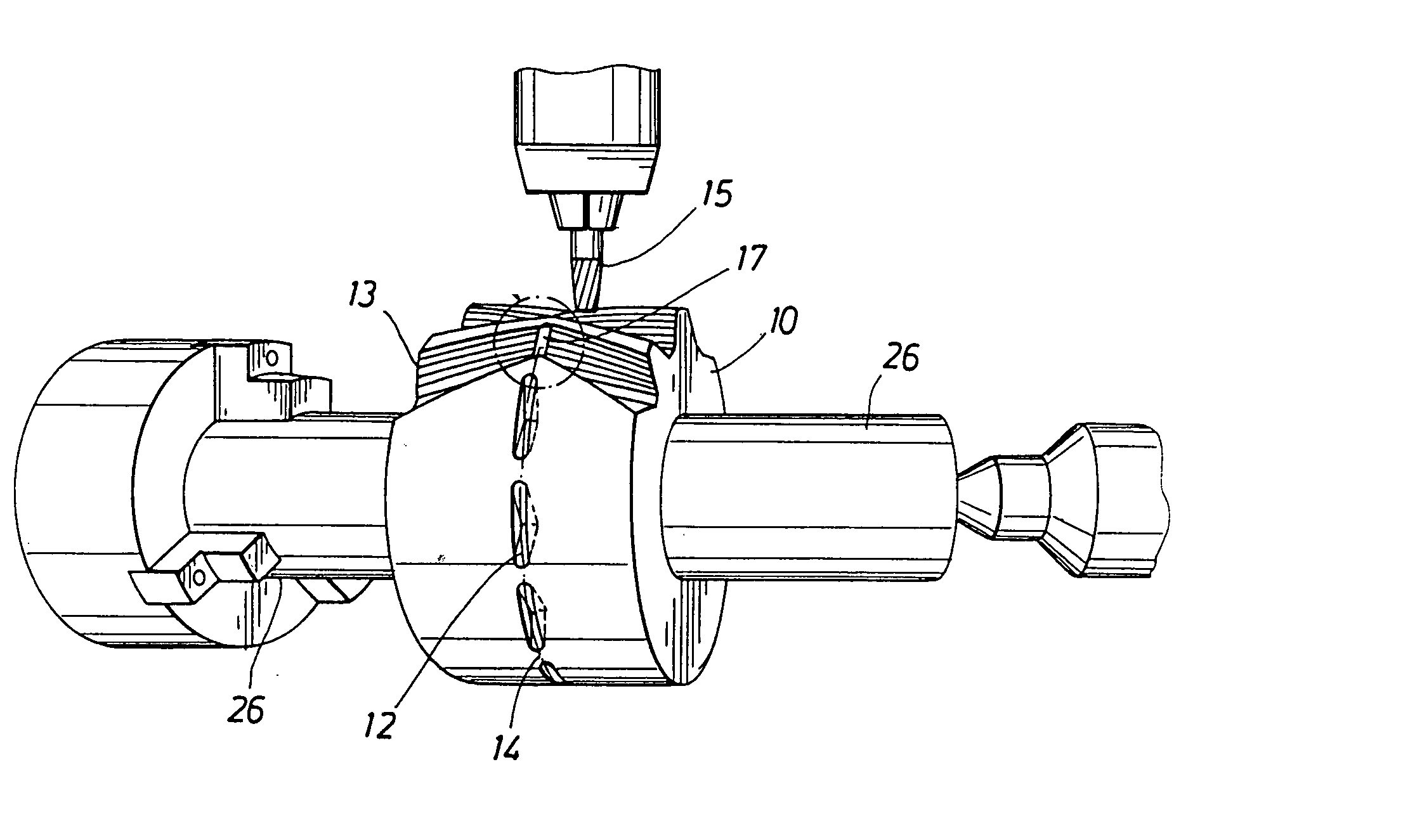
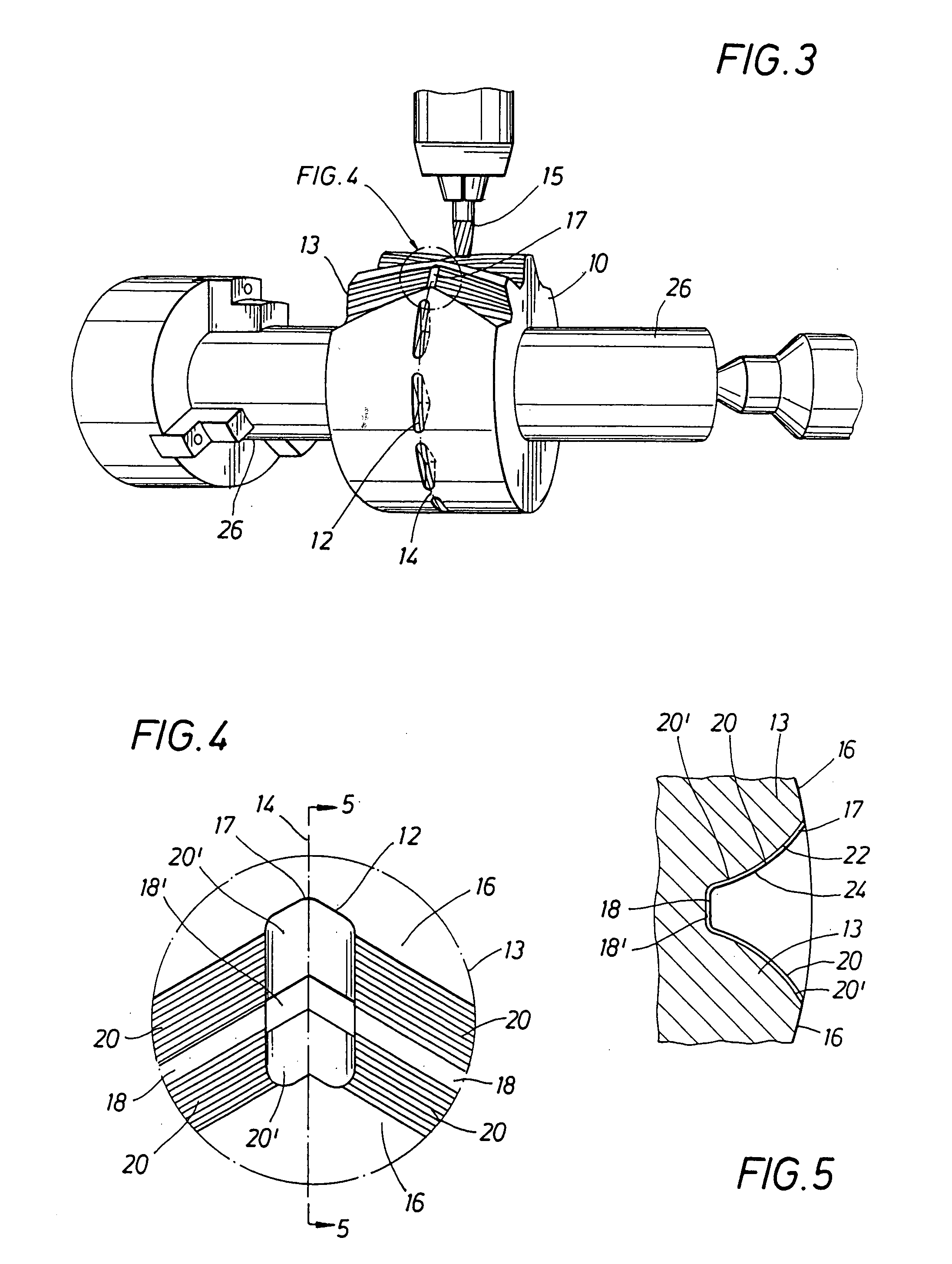
[0027] Referring to FIG. 3, the method according to the invention begins with machining of unhardened high quality steel stock 10 to develop the cylindrical features of the gear part. Next a series of relief notches 12 is machined for each tooth 13 in the gear. The relief notches 12 allow tool run-out in the subsequent finishing process. While the Sykes-cut herringbone gear has a slight furrow at the acute intersection of the two helices formed from the cutting action of the gear generator, the furrow does not provide sufficient clearance for finishing process of this invention.

[0028] Relief notches 12 are generated by machining a series of involute cuts in the part at the apex 14 (where the helices meet) between each two adjacent teeth 13 around the circumference of the part 10. A relief notch 12 is initially machined in the center of the gear face, the apex 14. The part 10 is rotated a pre-determined amount and the milling head 15 is indexed axially an amount to duplicate the heli...


PUM

PropertyMeasurementUnit
depthaaaaaaaaaa
depthaaaaaaaaaa
depthaaaaaaaaaa

Abstract

A method of manufacturing herringbone gears starting with non-hardened cylindrical stock material, establishing a relief notch for each tooth in the cylindrical stock where the two helices meet, roughing the double helical teeth, and case-hardening the gear teeth. The teeth are then finished using high accuracy Cubic Borzon Nitride (CBN)-faced cutters with the relief notch allowing run-out of the cutters.

Description

[0001] This application is based upon provisional application 60 / 402,266 filed on Aug. 8, 2002, the priority of which is claimed.[0002] 1. Field of the Invention[0003] This invention relates generally to gear teeth, in particular herringbone gear teeth and improvements in methods for their manufacture.[0004] 2. Description of the Prior Art[0005] Helical gears, which have teeth cut at an acute angle to the axis, are designed to have numerous teeth meshing at all points of rotation and to distribute pressure evenly along the entire length of each tooth. Thus, they provide smooth operation and reliability, and they are ideal for power transmission applications. Because of the angle of the teeth on a single helix gear (also referred to as a twisted spur gear), an axial thrust is created, but by using two opposing helices at complementary angles, induced axial thrust is eliminated.[0006] The performance of a precision gear is largely determined by tooth accuracy and surface characteristi...

Claims


Application Information

Patent Timeline
Patent Type & Authority Applications(United States)
IPC IPC(8): B23F7/00F16H55/08B23P15/14F16H55/17
CPCB23F7/00B23P15/14Y10T29/49467Y10T29/49462Y10T74/19953Y10T29/49476
Inventor JINKINS, DAVID L.BECKMAN, KENNETH O.FRANKS, SCOTT A.NELSON, ARTRHUR L.
Owner LUFKIN GEARS LLC
Learn More