Gas dischargeable panel

a dischargeable panel and gas technology, applied in the direction of instruments, static indicating devices, electrodes, etc., can solve the problems of increasing the need for pdps power consumption, increasing the need for pdps technology to achieve low power consumption, and difficult stable production, so as to achieve reduced power consumption, reduced loss of visible light, and improved reflectivity

Inactive Publication Date: 2004-02-19
PANASONIC CORP
View PDF3 Cites 58 Cited by
  • Summary
  • Abstract
  • Description
  • Claims
  • Application Information

AI Technical Summary

Benefits of technology

0091] Ag or Cr/Cu/Cr). The use of Ag as the metal material allows the reflectivity to increase and the loss of visible light to be suppressed, and so contributes to higher illumination efficiency.
0092] The above size and position of each part of the display electrode are determined so that the discharge current waveform when driving the PDP has a si

Problems solved by technology

Due to the recent increases in the size and resolution of PDPs, the power consumption for PDPs tends to increase.
This heightens the needs for technologies that achieve lower power consumption.
However, when such a structure is used, the following problem arises.
A

Method used


Image

  • Gas dischargeable panel
  • Gas dischargeable panel
  • Gas dischargeable panel

Examples


first embodiment

[0104] on the other hand, there is only one discharge current peak. Hence stable sustain discharge can be performed when compared with the case where a plurality of peaks occur. This enables the gray scale control by pulse modulation to be exercised with stability, with it being possible to ensure excellent display performance.

[0105] In the first embodiment, the discharge current waveform has a single peak. Accordingly, the discharge illumination waveform has a single peak, too.

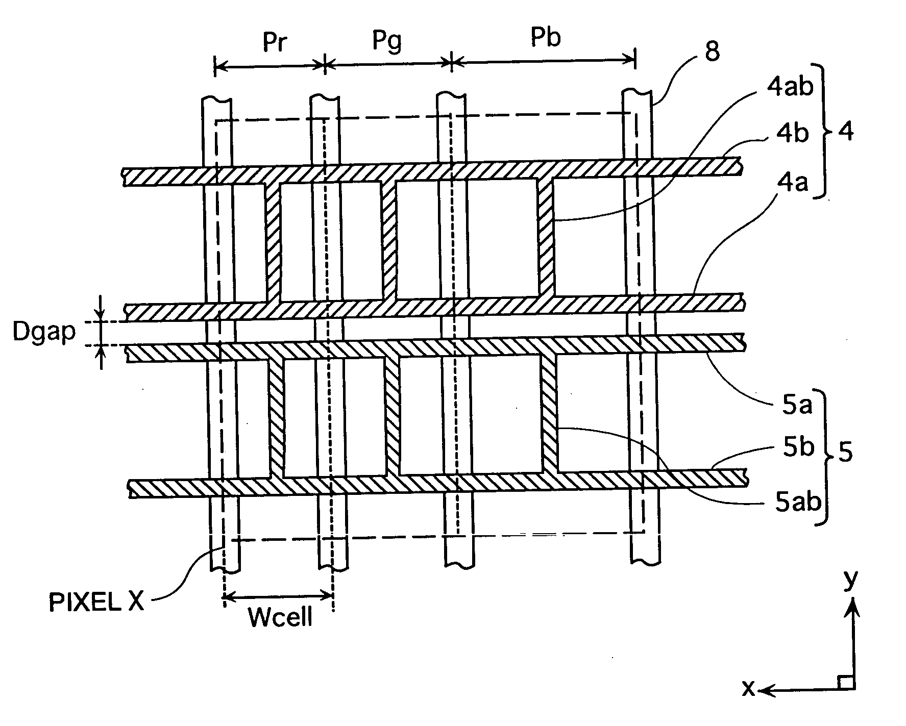
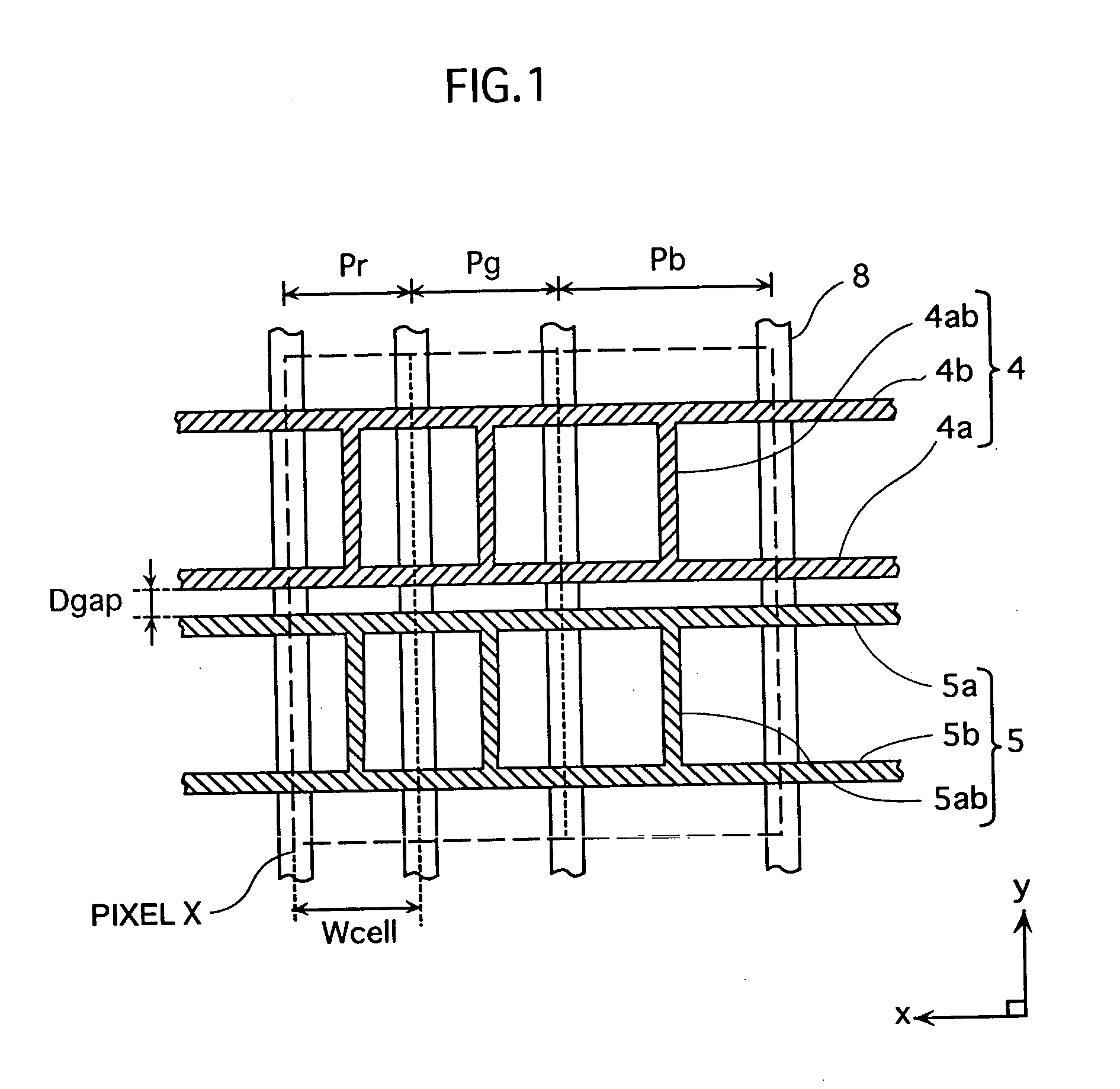
[0106] In the first embodiment, the above display electrode pattern is applied to a construction where the cell width in the x direction differs for each color of red, green, and blue. By doing so, variations in discharge firing voltage among the three colors of red, green, and blue are eliminated. As a result, a stable image display can be produced.

[0107] FIG. 3A is a graph showing the correlation between the widths of the line parts 4a, 4b, 5a, and 5b and the panel luminance. The widths of the line parts 4...

second embodiment

[0157] (Second Embodiment)

[0158] 2-1. Structure of a Display Electrode

[0159] The second embodiment is fundamentally based on the first embodiment, but is characterized in that a display electrode is made up of three or more line parts 4a, 4b, . . . and connector parts 4ab, 4bc, . . . which are arranged in he y direction in a straight line to connect the line parts.

[0160] FIG. 10 shows an example of the display electrode structure of the second embodiment. In the drawing, the scan electrode 4 (sustain electrode 5) has three line parts 4a-4c (5a-5c) that are connected by connector parts 4ab and 4bc (5ab and 5bc) arranged in a straight line in the y direction. The distance Dab between the line parts 4a and 4b (5a and 5b) is equal to the distance Dbc between the line parts 4b and 4c (5b and 5c). It is preferable for Dab and Dbc to be larger than the main discharge gap Dgap, to increase the opening ratio. As a result, high luminance can be obtained, and the voltage can be further reduced...

third embodiment

[0201] (Third Embodiment)

[0202] 3-1. Structure of a Display Electrode

[0203] In the first and second embodiments, a display electrode is made up of at least two line parts and at least one connector part which electrically connects the line parts, when the red cell, the green cell, and the blue cell have different widths in the x direction.

[0204] In the third embodiment, the display electrode 4 (5) includes three line parts 4a-4c (5a-5c) and projection parts 4aq and 4bq (5aq and 5bq) which are each provided on one side of any of the line parts 4a and 4b (5a and 5b) as a discharge developing part, as shown in FIG. 17. Here, the projection parts 4aq and 4bq (5aq and 5bq) have a rectangular shape, and are formed so as to extend in the y direction.

[0205] These projection parts 4aq and 4ba (5aq and 5bq) are formed such that the gap between adjacent line parts (e.g. 4a and 4b (5a and 5b)) is smaller in the areas corresponding to the channels between adjacent barrier ribs 8 than in the area...


PUM


Abstract

A gas discharge panel includes a first substrate and a second substrate. A plurality of display electrode pairs which are each made up of a sustain electrode and a scan electrode are formed on the first substrate, and the first substrate and the second substrate are set facing each other with a plurality of barrier ribs in between so as to form a plurality of cells. In this gas discharge panel, at least one of the sustain electrode and the scan electrode includes: a plurality of line parts; and a discharge developing part which makes a gap between adjacent line parts smaller in areas corresponding to channels between adjacent barrier ribs than in areas corresponding to the barrier ribs.

Description

[0001] The present invention relates to a gas discharge panel such as a plasma display panel.[0002] Plasma display panels (PDPs) are one type of gas discharge panel. PDPs enable large-screen slimline televisions to be produced relatively easily, and so are receiving attention as next-generation display panels. Currently, sixty-inch models have already been commercialized.[0003] FIG. 26 is a partial sectional perspective view showing a main construction of a typical surface discharge AC (alternating current) PDP. In the drawing, the z direction is a direction along the thickness of the PDP, whilst the xy plane is a plane that is in parallel with the panel plane of the PDP. As illustrated, this PDP, is roughly made up of a front panel FP and a back panel BP which are set with their main surfaces facing each other.[0004] A front panel glass 2 serves as a substrate for the front panel FP. A plurality of pairs of display electrodes 4 and 5 (scan electrode 4 and sustain electrode 5) are f...

Claims


Application Information

Patent Timeline
IPC IPC(8): G09G3/20G09G3/291H01J11/12H01J11/22H01J11/24H01J11/26H01J11/32H01J11/34H01J17/49
CPCG09G3/2022G09G3/28H01J11/12H01J2211/323H01J11/32H01J2211/245H01J11/24G09G3/2927G09G2300/0426G09G3/291
Inventor NISHIMURA, MASAKIHIGASHINO, HIDETAKAMURAI, RYUICHITAKADA, YUUSUKENAGAO, NOBUAKIANDO, TORUKOSUGI, NAOKITACHIBANA, HIROYUKI
Owner PANASONIC CORP
Why Eureka
Try Eureka