Exercise machine

a technology of exercise machines and pedals, applied in the direction of gymnastic exercise, frictional force resistors, vehicle components, etc., can solve the problems of undesirable exercise regiment, machine drawback, and pedal-like action

Inactive Publication Date: 2004-02-19
GREENHOUSE INT
View PDF13 Cites 25 Cited by
  • Summary
  • Abstract
  • Description
  • Claims
  • Application Information

AI Technical Summary

Problems solved by technology

Such machines suffer the drawback that the action is pedal-like in that one arm pushes while the other pulls and vice versa.
This action does not provide continuous resistance for each of the pushing and pulling actions, and as such results in an undesirable exercise regiment.

Method used


Image

  • Exercise machine
  • Exercise machine
  • Exercise machine

Examples


Embodiment Construction

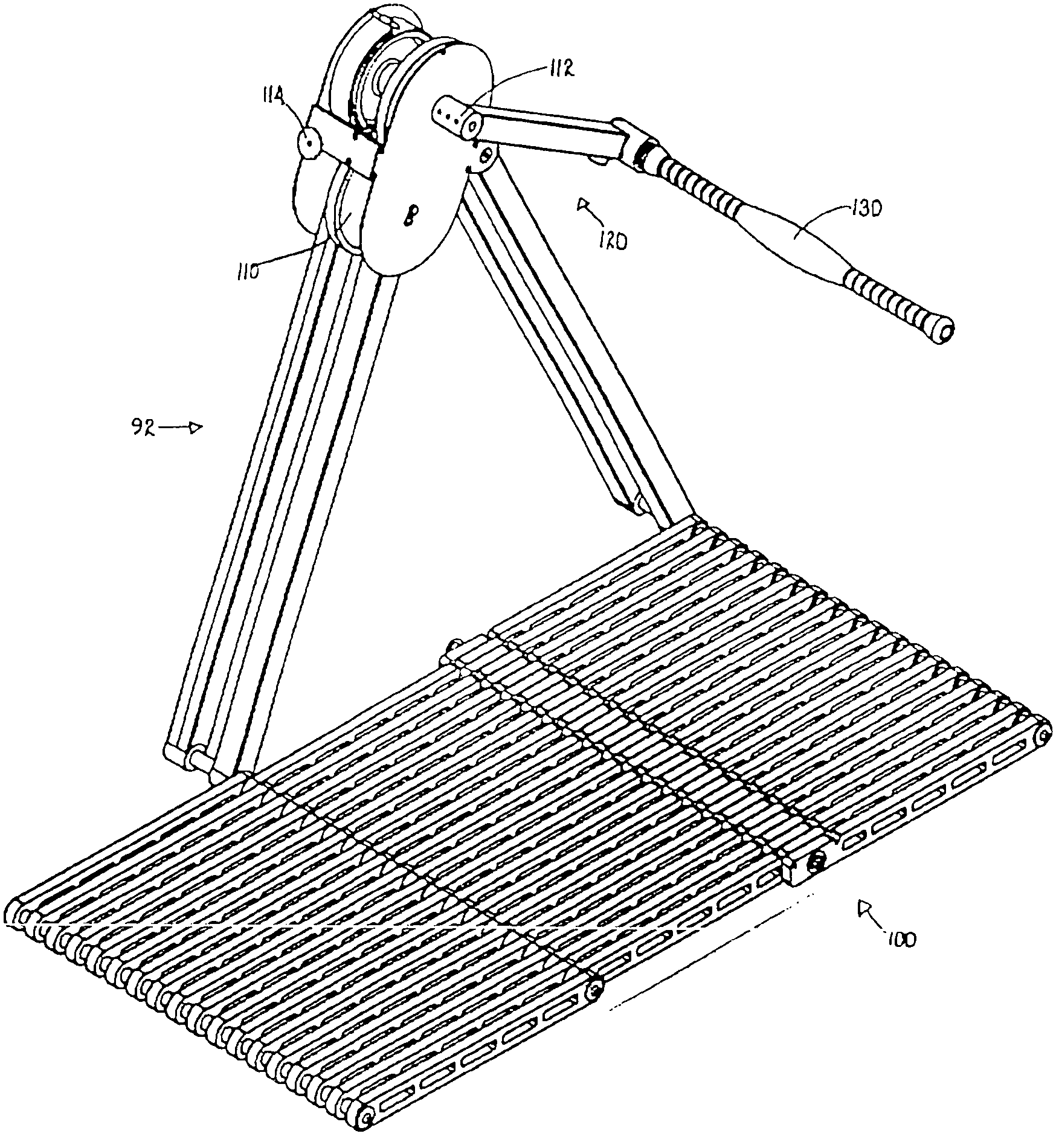
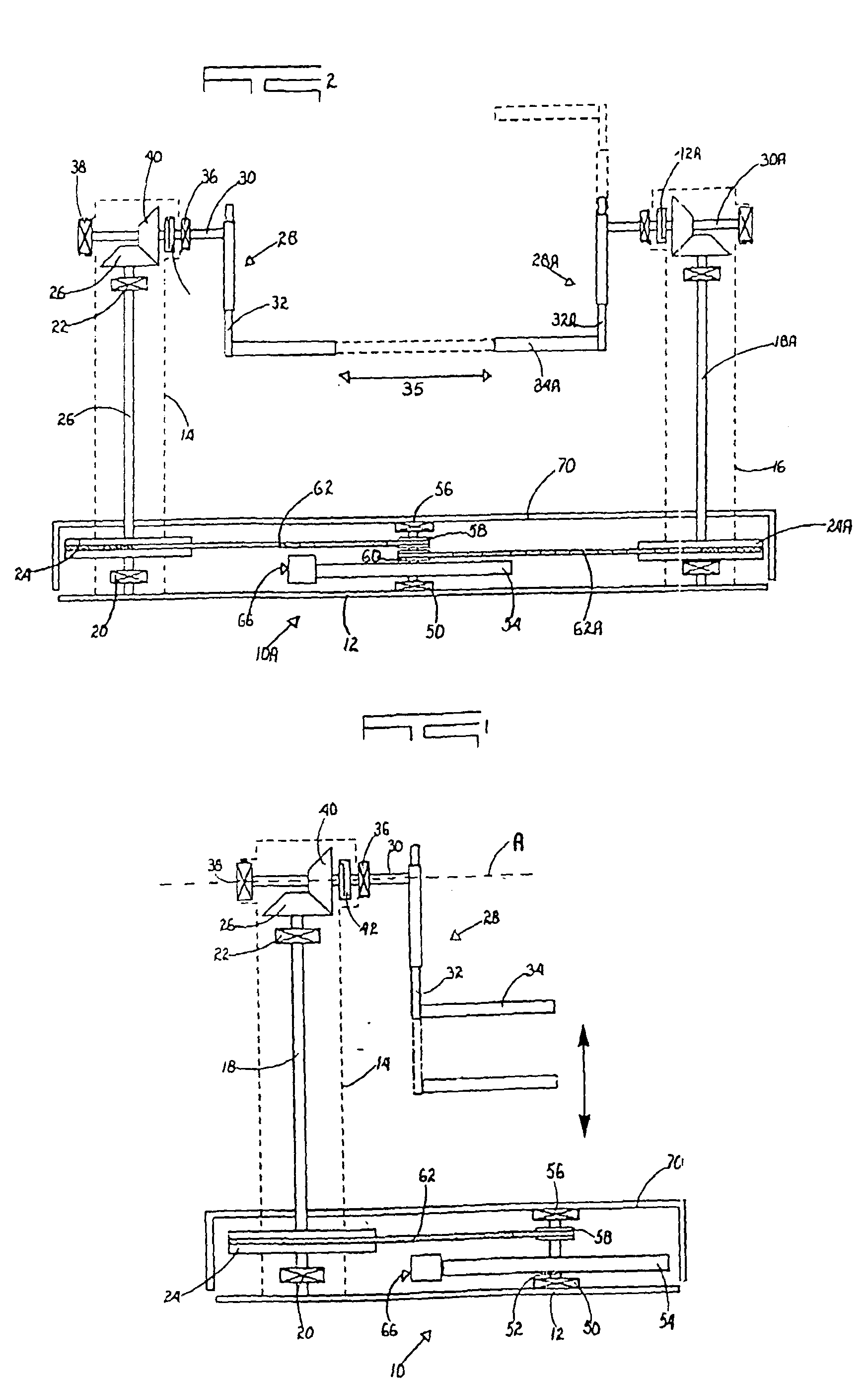
[0053] FIG. 1 of the accompanying drawings illustrates an exercise machine 10 according to a first form of the invention.

[0054] The machine 10 includes a base plate 12 which is mounted to an upwardly extending support column 14 which has a drive shaft 18 mounted, near opposed ends, to bearings 20 and 22 respectively. A relatively large drive pulley 24 is fixed to the drive shaft slightly above the bearing 20.

[0055] A bevel gear 26 is fixed to an upper end of the drive shaft.

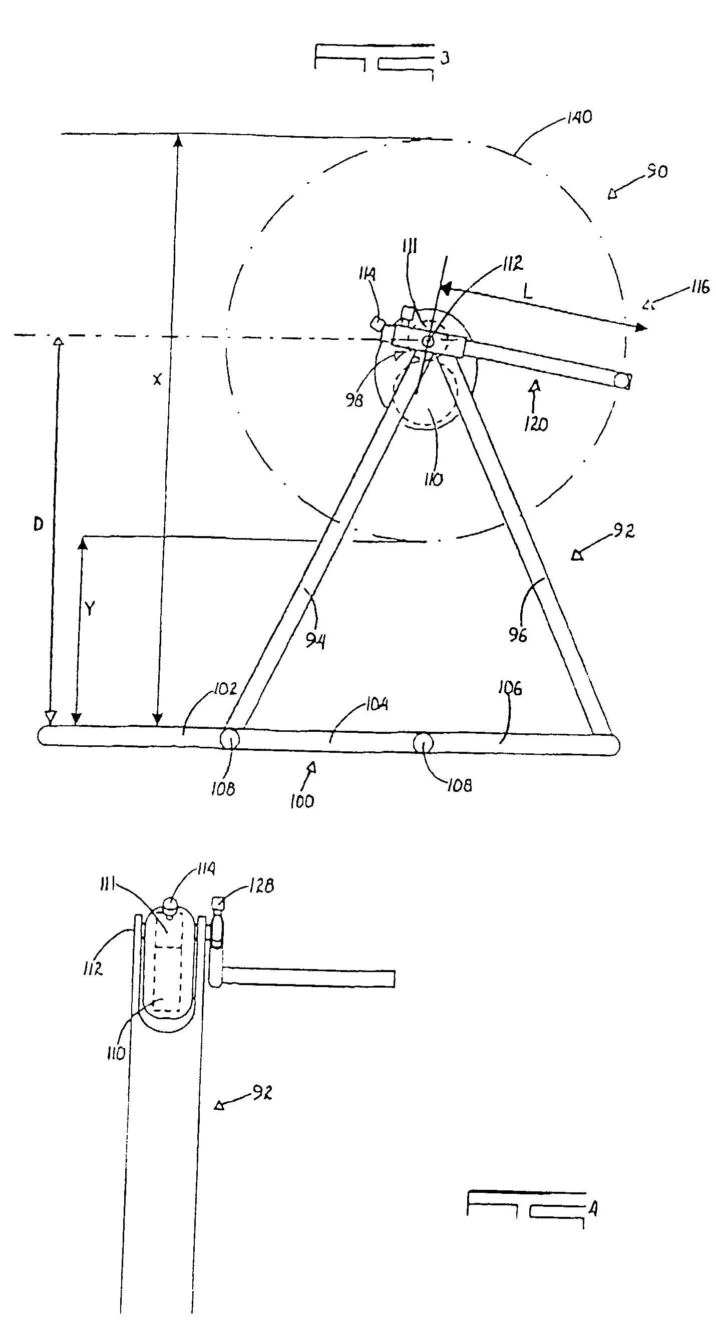
[0056] A cranked member 28 which includes a stub axle 30, a lever 32 and a handle 34, is fixed to an upper end of the support column 14. The stub axle extends horizontally, is mounted to bearings 36 and 38, and is centred on an axis A which defines an output point to components which form a drive arrangement in the machine. A bevel gear 40, which mates with the gear 26, is fixed to the axle. At a position between the bevel gear 40 and the bearing 38 an optional one-way drive mechanism in the nature of a ratchet 4...


PUM


Abstract

An exercise machine which includes a base upon which a user stands alongside an upwardly extending support. A handle, mounted to a lever rotatably fixed to the support, extends over the base so that the user can grip the handle with both hands and rotate the handle along a circular loop, alternately bending at the knees and then moving to an upright position, with arms extended, against a variable resistance force which is generated by a flywheel connected via a drive mechanism to the lever.

Description

[0001] 1. Field of the Invention[0002] This invention relates to exercise machines, and in particular to an exercise machine that provides continuous load exerting resistance for the user.[0003] 2. Prior Art[0004] Exercise machines that utilize bicycle like motion for hands and feet are well known in the art. Such machines suffer the drawback that the action is pedal-like in that one arm pushes while the other pulls and vice versa. This action does not provide continuous resistance for each of the pushing and pulling actions, and as such results in an undesirable exercise regiment.[0005] The invention provides an exercise machine which includes a support structure, a resistance assembly which is connected to the support structure, a drive member with an output point from which force is applied to the resistance assembly and an input point which is spaced from the output point by a distance L, and at least one handle which acts on the drive member at the input point and which a user ...

Claims


Application Information

Patent Timeline
Patent Type & Authority Applications(United States)
IPC IPC(8): A63B21/005A63B21/012A63B21/22A63B22/06A63B22/10B62M3/02
CPCA63B21/005A63B21/012A63B21/225A63B22/0002A63B22/0605A63B2022/0005A63B21/00192A63B2022/0617A63B2022/0623A63B2208/0204A63B2210/50B62M3/02A63B21/1496A63B2022/0035A63B21/4049A63B22/0005
Inventor VAN STRAATEN, WILLEM JOHANNES
Owner GREENHOUSE INT
Why Eureka
Try Eureka