

Method of manufacturing image forming apparatus
- Summary
- Abstract
- Description
- Claims
- Application Information
AI Technical Summary
Benefits of technology
Problems solved by technology
Method used
Image

Examples
first embodiment
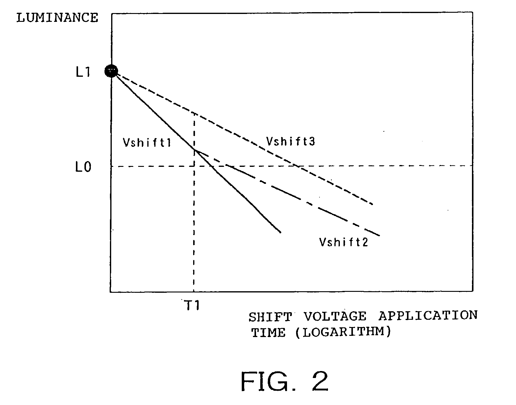
[0157] Firstly, as described in the first embodiment, the luminance target value L0 is determined on the basis of the average luminance and the standard deviation.
[0158] In this example, the target luminance L0 is set at 9600 (a.u.). In addition, the value of the luminance is a value which corresponds to the luminance obtained from CCD.
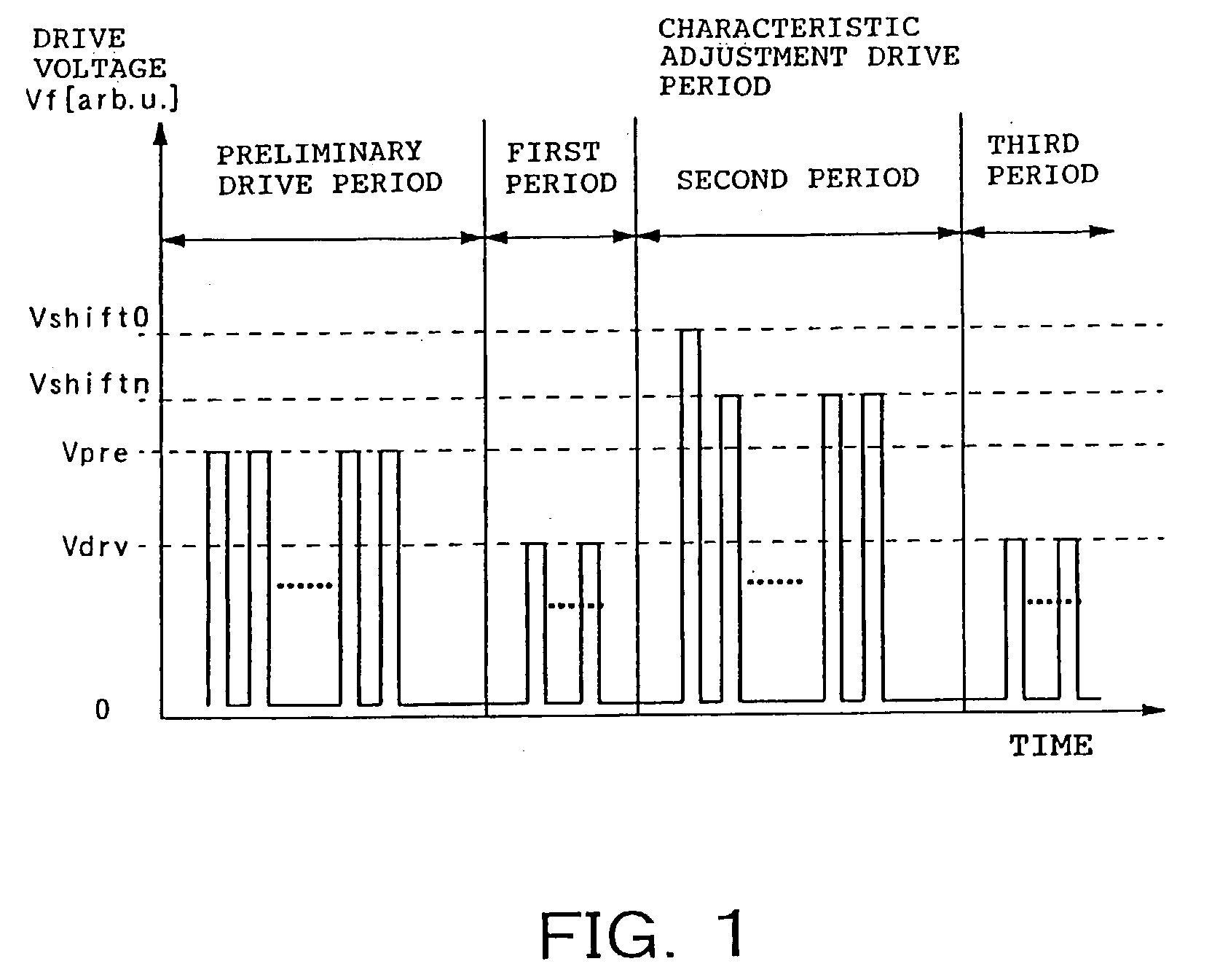
[0159] Next, pulse width is set to 1 msec, and cycle is set to 10 msec, and others are set to satisfy Vpre=16V, Vdrv=14.5V, Vshift1=16.5V, Vshift2=17V, Vshift3=17.5V, Vshift4=18V, Vshift1'=16V, Vshift2'=16.5V, and Vshift3'=17V. And, as described in the first embodiment, the look-up table was prepared.
[0160] Hereinafter, procedures of characteristic adjustment method will be described by use of a flow chart of FIG. 7.
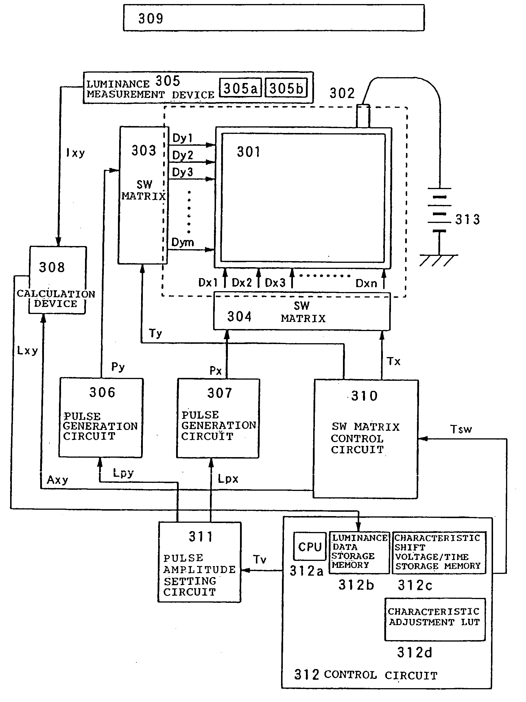
[0161] Firstly, at Step S1, set is the number of applied pulses which are applied at the time of characteristic adjustment to one of SCE-emitters to which the characteristic adjustment is carried out in the display panel 301. The number of...
example 2
[0176] As described above, there exist a small number of electron sources in which rates of changes to the number of applied pulses in the characteristic variation curves shown in FIG. 6 differ greatly. In this example, even as to such electron sources, by incorporating a way, described later, of coping with them into the steps (1) and (2) for adjusting the characteristic of large majority of the electron sources, it became possible to adjust the characteristic thereof.
[0177] Here, a method of setting characteristic shift voltages and a method of adjusting characteristics which are different from those of the example 1 will be described. As to other processes, similar techniques to the example 1 were used and therefore, descriptions thereof will be omitted. Also, SCE-emitters used and voltage setting were made to be the same as the example 1. Further, the luminance target value L0 is also set at 9600 (a.u).
[0178] As the electron source which did not reach the vicinity of the target ...
example 3
[0203] In this example, correction of the characteristic voltage which was carried out in the example 2 was carried out with respect to each pulse. Here, a method of setting characteristic shift voltages and a method of adjusting characteristics which are different from those of the example 1 will be described. As to other processes, similar techniques to the example 1 were used and therefore, descriptions thereof will be omitted.
[0204] Compared are shift amount calculated from luminance Lp (before application) and Lp' (after application) at the time of applying Vdrv before and after the characteristic shift voltage pulse is applied and shift amount which was estimated. Assuming that the estimated shift amount is Dn, actual shift amount Dr becomes Dr=L1' / L1, from the luminance Lp before the application of one pulse of the characteristic shift voltage and luminance L1' after that.
[0205] A difference .DELTA.D of the shift amounts is described as .DELTA.D=Dn-Dr.
[0206] Thereby, it has b...
PUM
 Abstract
Description
Claims
Application Information