Coil bobbin with core spacing mechanisms

Inactive Publication Date: 2004-02-26
MINEBEA CO LTD
View PDF4 Cites 21 Cited by
  • Summary
  • Abstract
  • Description
  • Claims
  • Application Information

AI Technical Summary

Problems solved by technology

While the varnish impregnation treatment improves insulation performance of the winding section and also stabilities against electrical oscillation and mechanical oscillation, it creates the following problem.
However, the coil bobbin formed of the thermoplastic resin (polyb

Method used


Image

  • Coil bobbin with core spacing mechanisms
  • Coil bobbin with core spacing mechanisms
  • Coil bobbin with core spacing mechanisms

Examples


Embodiment Construction

[0026] Preferred embodiments of the present invention will hereinafter be described with reference to the accompanying drawings.

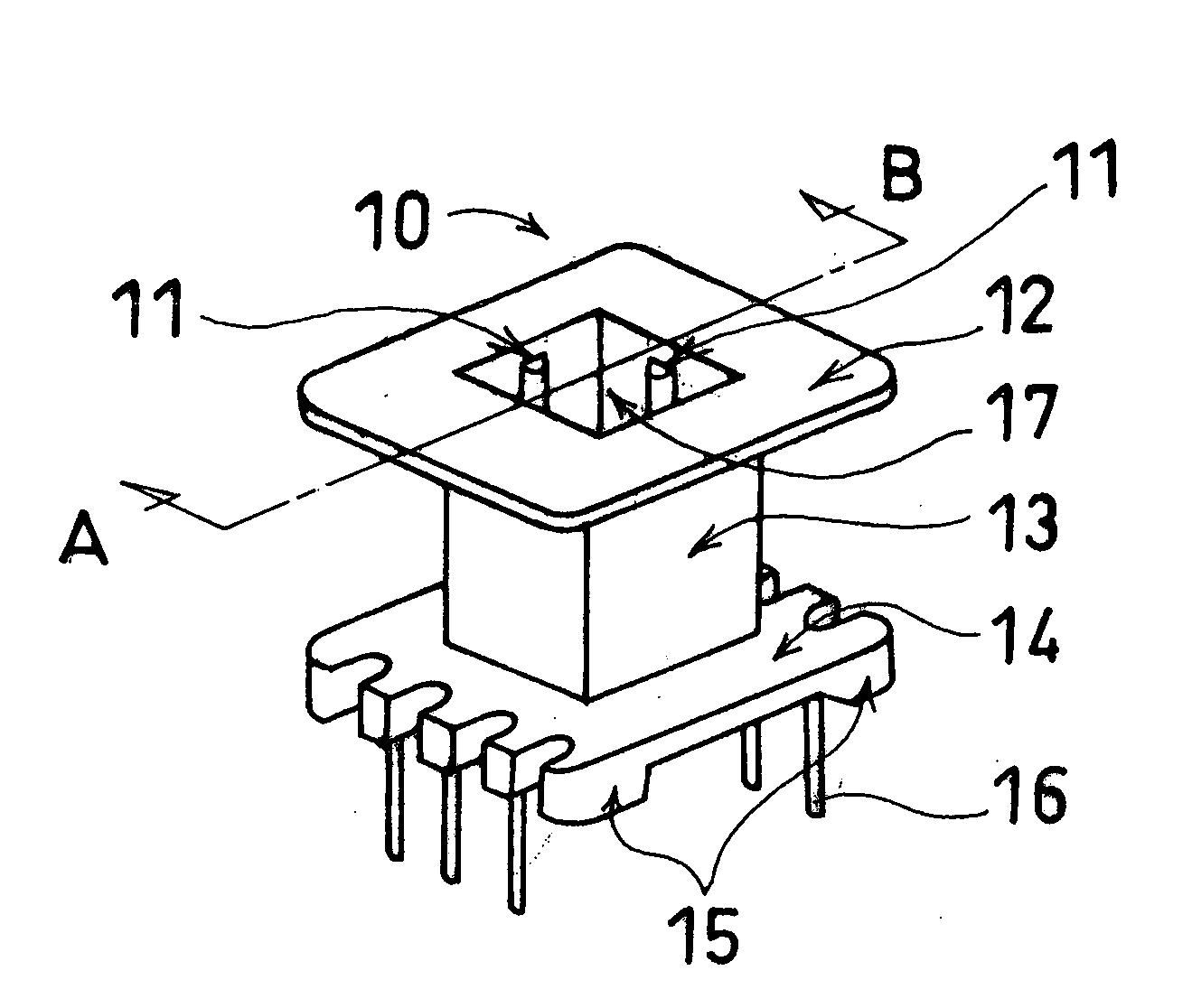
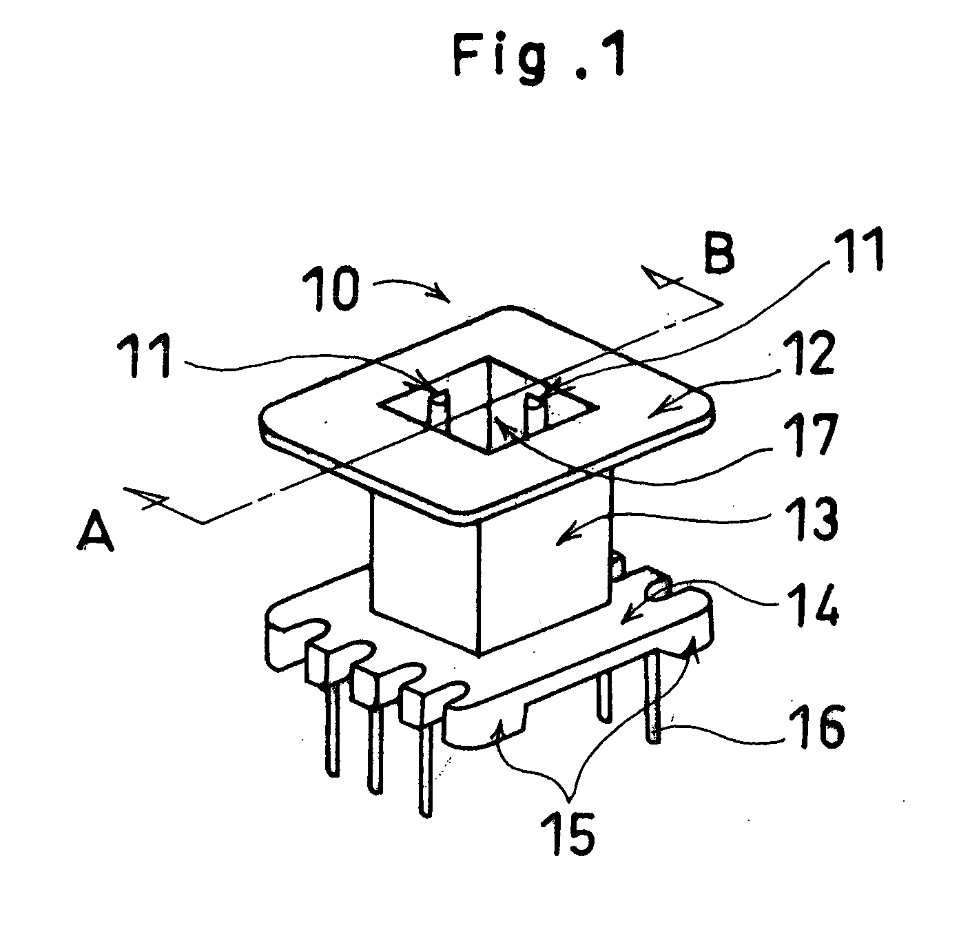
[0027] Referring to FIG. 1, a coil bobbin 10 comprises a top flange 12, a base flange 14, and a core housing portion 13 formed therebetween. The base flange 14 has terminal pins 16 to which a winding (not shown) is connected, and is provided with coil stand portions 15. The core housing portion 13 is of square tubular structure, has a magnet wire (not shown) wound therearound, and has at least one core spacing mechanism 11 provided on each of four surfaces of its inner wall 17 and formed into a linear ridge extending straight in the direction of inserting the magnetic core.

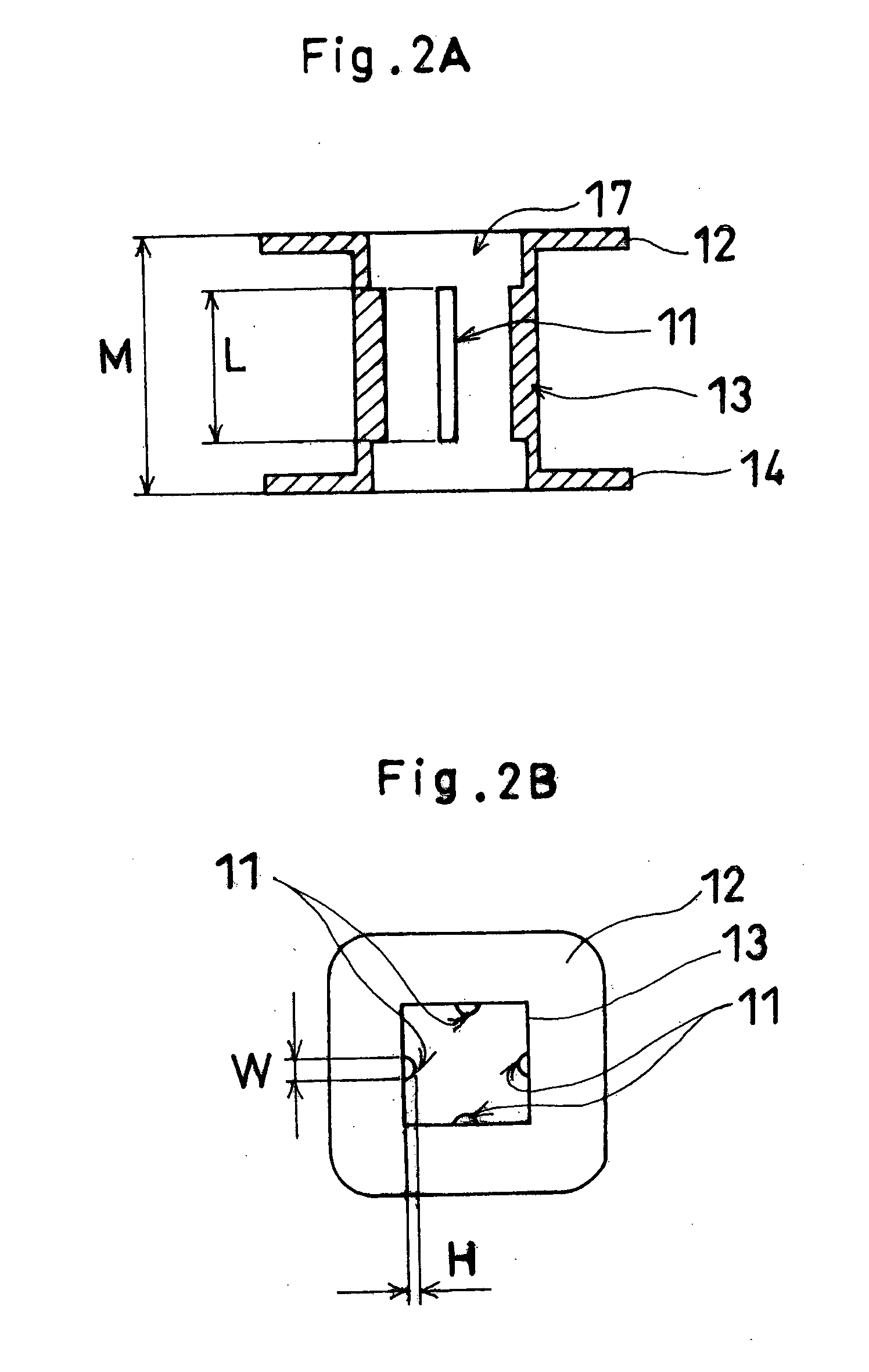
[0028] Referring now to FIGS. 2A and 2B, each of the core spacing mechanisms 11 has a length L smaller than a length M of the core housing portion 13, which is defined by the distance from the outside of the top flange 12 to the outside of the base flange 14. Also, as described later with...


PUM


Abstract

A coil bobbin comprises a core housing portion which has a magnet wire wound therearound, and which undergoes a varnish impregnation treatment together with a magnetic core consisting of two core sections, like an EE type or UU type. Core spacing mechanisms are formed on the inner surfaces of the core housing portion, and control a position of the magnetic core inserted in the core housing portion such that the magnetic core is kept apart from the inner surfaces of the core housing portion.

Description

[0001] 1. Field of the Invention[0002] The present invention relates to a coil bobbin, and particularly to a coil bobbin which undergoes a varnish impregnation treatment together with a magnetic core.[0003] 2. Description of the Related Art[0004] A conventional transformer or choke coil comprises a magnetic core using a ferrite core and a plastic bobbin having a magnet wire wound therearound. The magnetic core consists of two separate sections like EE type, or UU type, where the two separate core sections abut against each other to form a closed magnetic path. In the structure, a gap may grow at the abutting contact portion and acts as a critical factor determining magnetic characteristics of the core. The abutting contact condition may be secured by adhesively bonding, taping or by means of a metallic spring.[0005] The transformer or choke coil may undergo a well-known varnish impregnation treatment together with its magnetic core depending on its application. The treatment is to i...

Claims


Application Information

Patent Timeline
IPC IPC(8): H01F5/02H01F27/02H01F27/26H01F27/32
CPCH01F27/022H01F27/325H01F27/263
Inventor SUZUKI, MITSUAKI
Owner MINEBEA CO LTD
Why Eureka
Try Eureka