This helps you quickly interpret patents by identifying the three key elements:
Problems solved by technology
Method used
Benefits of technology
Problems solved by technology
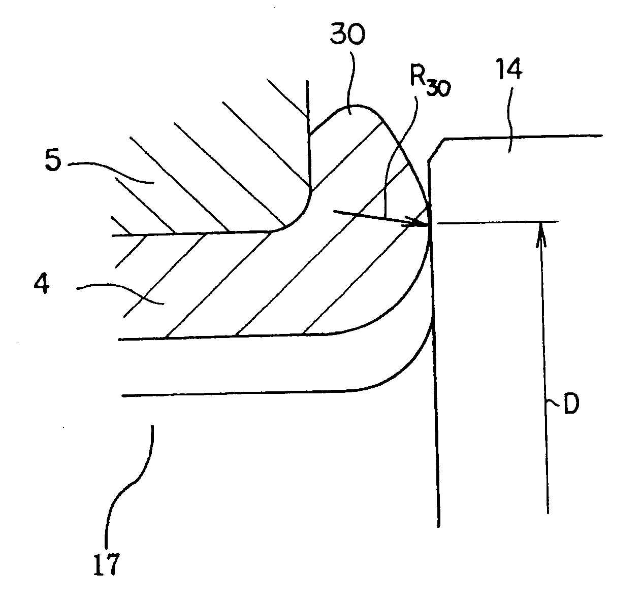
In this case, as the friction force acting on the area of contact becomes large, the rubbing energy between the surface on the inside end of the inner race 5 and the surface on the outside end of the outer ring 14 of the constant-velocity joint becomes large due to the slipping, and cause an unpleasant noise.
However, the film for reducing the friction is not always durable enough, and it is difficult to maintain sufficient effect over a long period of time.
Particularly, with construction of not sealing the contact area with a seal ring, the period of time that the unpleasant noise can be effectively reduced is limited.
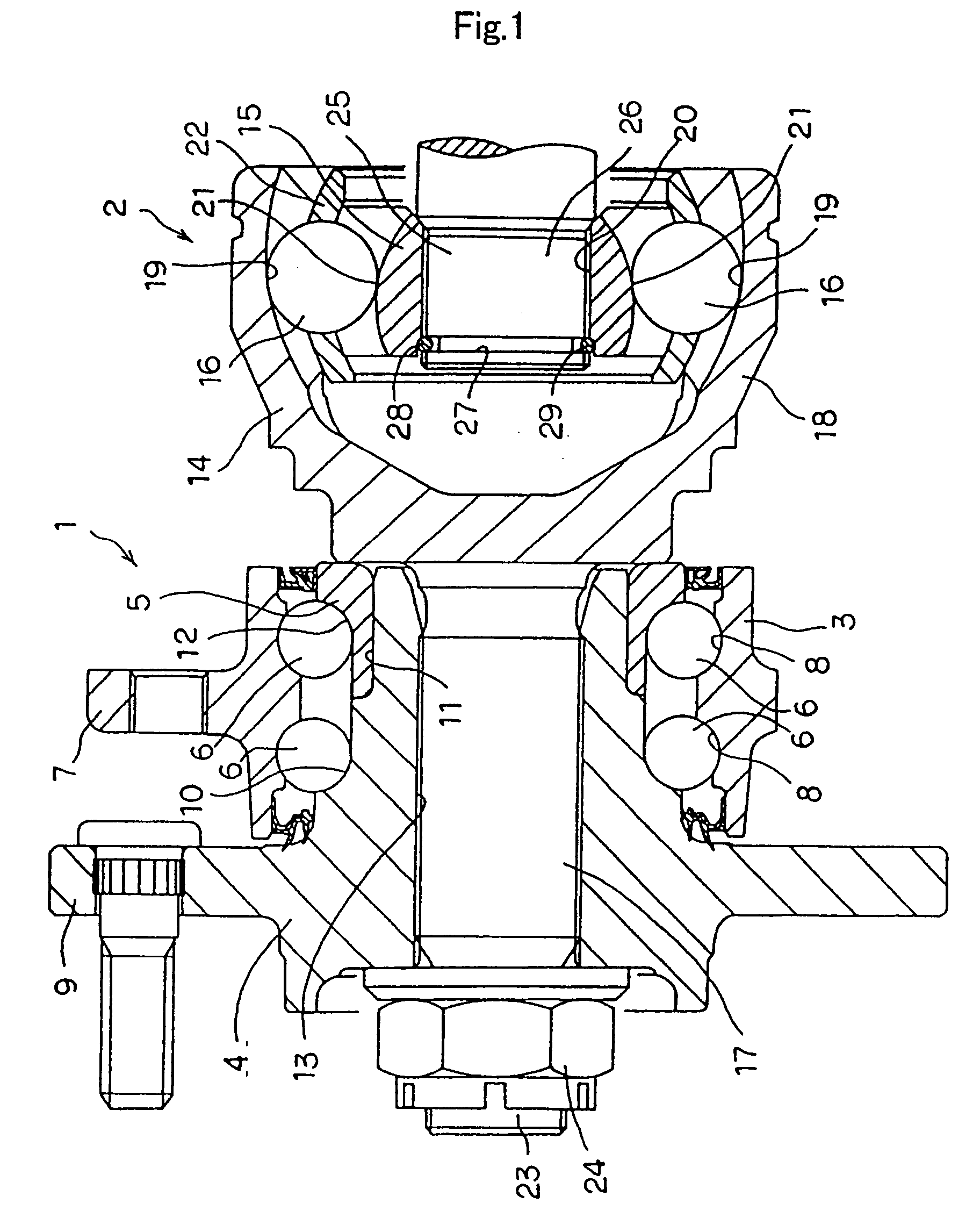
However, in the case of the first example of prior art construction shown in FIG. 1, a pre-load is applied to the rolling elements 6 due to the tightening force of the nut 24, so application of this method is difficult.
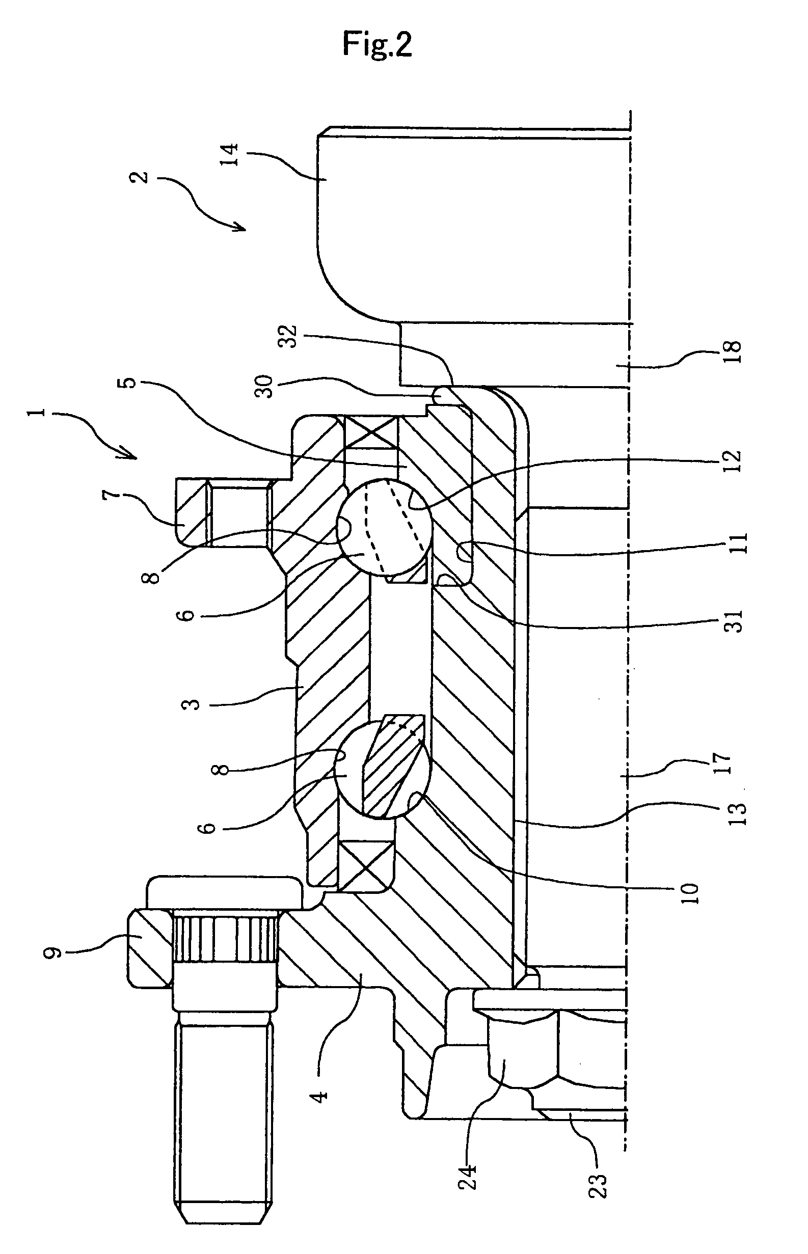
In the case of the second example shown in FIG. 2 as well, increasing the tightening force of the nut 24 as in the case of the first example is considered, so it is not possible to suppress the occurrence of the unpleasant noise.
Therefore, the torque required for tightening the nut 24 becomes large, and it is not possible to avoid decrease in work efficiency of assembling the bearing unit for wheel drive.
Moreover, in the case of the second example shown in FIG. 2, the cost increases due to the work of tightening the nut 24 with a large torque.
Method used
Image
Click on the blue label to locate the original text in one second.
Reading with bidirectional positioning of images and text.
Examples
first embodiment
[0042] Similar to the second example of prior art construction shown in FIG. 2, the bearing unit for wheel drive of the invention comprises a drive-shaft member, hub, flange, first inner-ring raceway, small-diameter stepped section, inner race, outer race and rolling elements.
[0043] On the inside half of the drive-shaft member there is an outer ring for the constant-velocity joint, and on the outside half there is a spline shaft.
[0044] Also, a spline hole is formed in the center of the hub in which the spline shaft is fitted, such that the hub is rotated and driven by way of the constant-velocity joint during use.
[0045] In addition, the flange is formed around the outer peripheral surface on the outside end of the hub in order to support and fasten the wheel to the hub.
[0046] Moreover, the first inner-ring raceway is formed directly around the outer peripheral surface in the middle of the hub, or by way of another inner race that is separate from the hub.
[0047] Also, the small-diame...
second embodiment
[0055] Moreover, unlike the second example of prior art construction as shown in FIG. 2, in the present invention, there is no flat surface formed on the surface of the inside end of the crimped section, and it is preferable that the cross-sectional shape of the crimped section be left as is with a convex circular arch shape, such that there is line contact between the surface on the inside end of the crimped section and the surface on the outside end of the outer ring of the constant-velocity joint.
[0056] Also, in the bearing unit for wheel support of this invention, it is preferable that the load per unit length F / L.sub.a that is obtained by dividing the axial force F, which is applied to the spline shaft when the nut is tightened, by the circumferential length L.sub.a around the average diameter of the contact area between the surface on the inside end of the crimped section and the surface on the outside end of the outer ring of the constant-velocity joint, be 125 N / mm or less. ...
PUM
Abstract
An inner race 5 is retained by a crimped portion 30, so that a pre-load is applied to rolling elements 6. A bearing unit for wheel support 1 is connected to a constant velocity joint 2 through tightening of a nut 24. By regulating the tightening force of the nut 24, at the area of contact between the inside end of the crimped portion 30 and the outside end of the outer ring of the constant velocity joint 14, the load per unit length is controlled up to 125 N / mm, or the surface pressure is controlled up to 1.5x10<8 >Pa. Consequently, a bearing unit for wheel support is realized at a low cost with the pre-load securely applied, preventing unpleasant noise from occurring during operation, and preventing play due to plastic deformation.
Description
[0001] This invention relates to a bearing unit for wheel drive, and more particularly to a bearing unit for wheel drive which integrates a bearing unit for supporting the wheels with a constant-velocity joint, and which is used for supporting the drive wheels that are supported by an independent suspension {front wheels of a FF vehicle (front engine and front-wheel drive vehicle), the rear wheels of a FR vehicle (front engine and rear-wheel drive vehicle), and all the wheels of a 4WD vehicle (four-wheel drive vehicle)} such that they rotate freely with respect to the suspension, as well as for rotating and driving the drive wheels.BACKGROUND TECHNOLOGY OF THE INVENTION[0002] Various kinds of bearing units for wheel support, which are constructed such that an outer race and inner race rotate freely by way of rolling elements, have been used in order to support wheels such that they can rotate freely with respect to the suspension.[0003] Moreover, a bearing unit for supporting the dr...
Claims
Application Information
Patent Timeline
Application Date:The date an application was filed.
Publication Date:The date a patent or application was officially published.
First Publication Date:The earliest publication date of a patent with the same application number.
Issue Date:Publication date of the patent grant document.
PCT Entry Date:The Entry date of PCT National Phase.
Estimated Expiry Date:The statutory expiry date of a patent right according to the Patent Law, and it is the longest term of protection that the patent right can achieve without the termination of the patent right due to other reasons(Term extension factor has been taken into account ).
Invalid Date:Actual expiry date is based on effective date or publication date of legal transaction data of invalid patent.

