Sealing device and shock absorber with the sealing device

a sealing device and sealing technology, applied in the direction of shock absorbers, mechanical devices, springs/dampers, etc., can solve the problem of bringing discomfort to the user

Inactive Publication Date: 2014-07-24
KYB CORP
View PDF4 Cites 28 Cited by
  • Summary
  • Abstract
  • Description
  • Claims
  • Application Information

AI Technical Summary

Benefits of technology

[0016]The present invention aims to provide a sealing device capable of restraining working fluid leaked out from an oil seal lip from being scraped out to an outer side even if a high-friction oil seal is adopted and an opening occurs.
[0017]According to one aspect of the present invention, a sealing device adapted to seal an outer periphery of a shaft member movably inserted into a tubular member storing working fluid is provided. The sealing device includes a dust seal lip arranged on an outer side of the tubular member to prevent the entrance of foreign substances; and an o...

Problems solved by technology

However, since the dust seal lip 300 is so shaped that a working fluid film during a compression stroke in which the piston rod 2 enters the cylinder 1 is set to be thinner than that during an extension stroke of the piston rod 2 i...

Method used


Image

  • Sealing device and shock absorber with the sealing device
  • Sealing device and shock absorber with the sealing device
  • Sealing device and shock absorber with the sealing device

Examples


Embodiment Construction

[0025]Hereinafter, an embodiment of the present invention is described with reference to the drawings. The same reference signs assigned through several drawings denote the same or corresponding components.

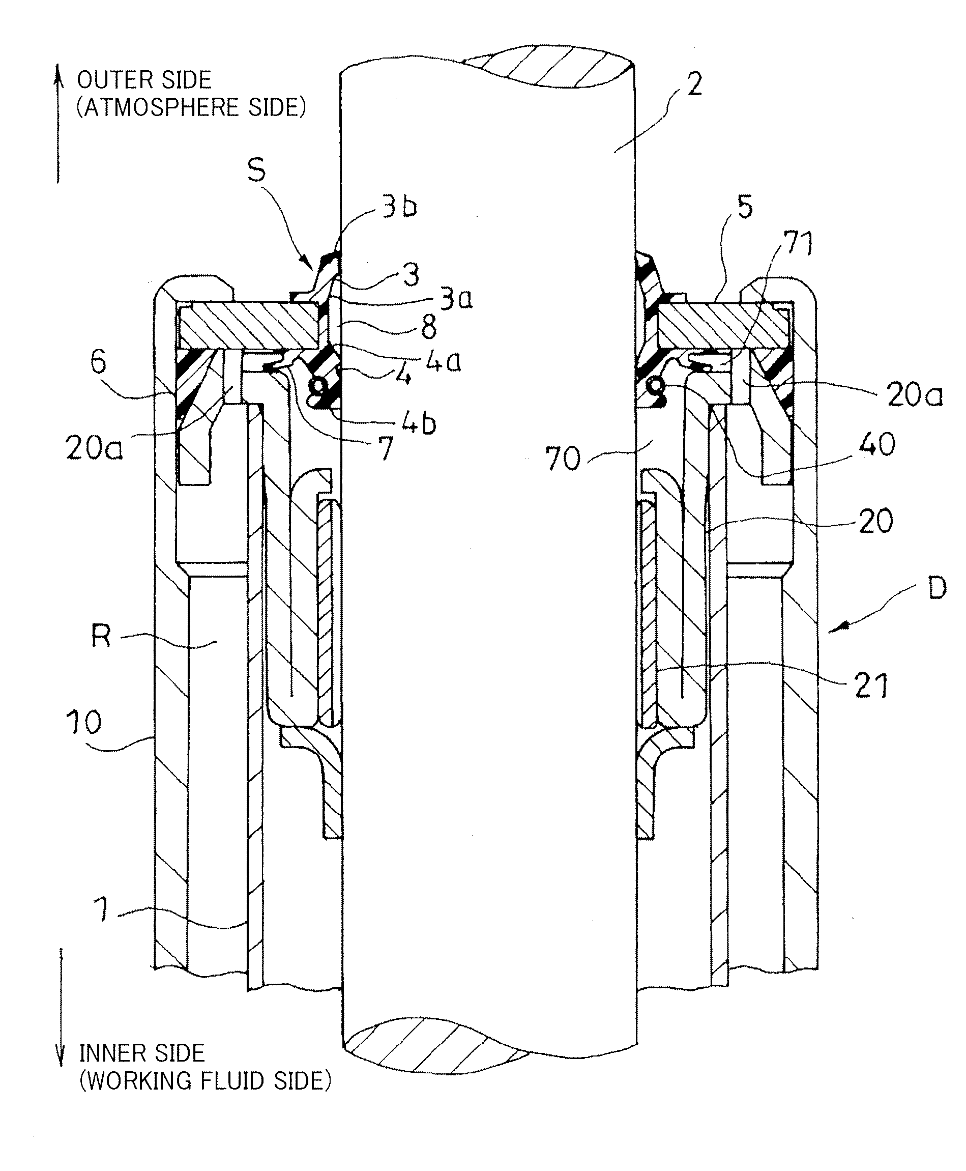
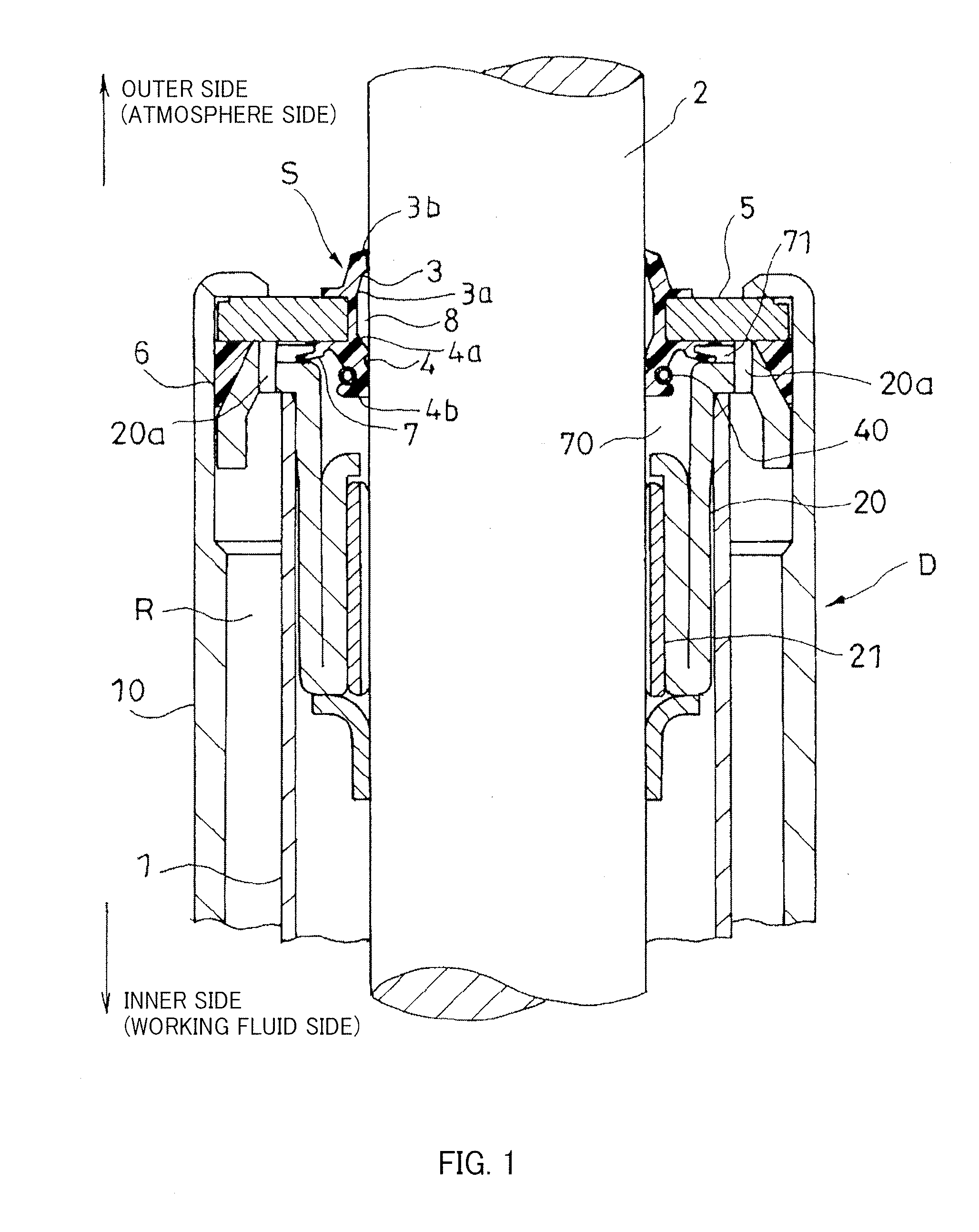
[0026]As shown in FIG. 1, a sealing device S seals the outer periphery of a piston rod (shaft member) 2 movably inserted into a cylinder (tubular member) 1 storing working fluid. The sealing device S includes a dust seal lip 3 which is arranged on an outer side (atmosphere side) of the cylinder 1 to prevent the entrance of foreign substances and an oil seal lip 4 arranged on an inner side (working fluid side) of the cylinder 1 to prevent the outflow of the working fluid. A space for accumulating the working fluid is formed between the dust seal lip 3 and the oil seal lip 4.

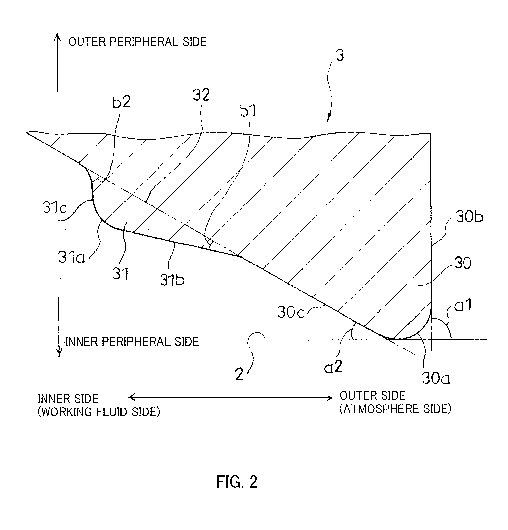
[0027]As shown in FIG. 2, the dust seal lip 3 includes a main lip portion 30 and an auxiliary lip portion 31 formed to be closer to an oil seal lip side (working fluid side) than the main lip portion 30. A maxim...


PUM


Abstract

A sealing device adapted to seal an outer periphery of a shaft member inserted into a tubular member includes a dust seal lip arranged on an outer side of the tubular member and an oil seal lip arranged on an inner side of the tubular member to form a space for accumulating working fluid between the oil seal lip and the dust seal lip. The dust seal lip includes a main lip portion and an auxiliary lip portion formed to be closer to the oil seal lip than the main lip portion. A maximum value of a surface pressure gradient absolute value of the inner side in the auxiliary lip portion is set to be larger than that of a surface pressure gradient absolute value of the outer side in the auxiliary lip portion.

Description

TECHNICAL FIELD[0001]The present invention relates to an improvement of a sealing device and a shock absorber with this sealing device.BACKGROUND ART[0002]A sealing device is used in a shock absorber for suppressing the vibration of a transport equipment or a building, a hydraulic drive cylinder device or the like and seals working fluid stored in the shock absorber, the cylinder device or the like.[0003]For example, JP2006-17161A discloses a sealing device used in a shock absorber for suspension for suppressing the transmission of vibration caused by uneven road surface to a vehicle body of an automotive vehicle by being interposed between the vehicle body and wheels.[0004]As shown in FIG. 4, the above sealing device S1 seals the outer periphery of a piston rod (shaft member) 2 movably inserted into a cylinder (tubular member) 1 in a shock absorber D. The sealing device S1 is laminated on an outer side (atmosphere side) than an annular rod guide 20, with the inner periphery of whic...

Claims


Application Information

Patent Timeline
IPC IPC(8): F16F9/36F16J15/32F16F9/32F16C33/72
CPCF16J15/3236F16F9/36F16J15/56
Inventor OZAKI, SHINJISAITA, SHUSAKUITO, KIYOAKIIMOTO, CHIKASHI
Owner KYB CORP
Why Eureka
Try Eureka