Liquid crystal display device and manufacturing method of liquid crystal display device

a technology of liquid crystal display device and manufacturing method, which is applied in the direction of liquid crystal compositions, instruments, chemistry apparatus and processes, etc., can solve the problems of insufficient purity of displayed colors, difficult to achieve high-resolution display, and increase in power consumption

Inactive Publication Date: 2004-03-04
FUJITSU LTD
View PDF5 Cites 6 Cited by
  • Summary
  • Abstract
  • Description
  • Claims
  • Application Information

AI Technical Summary

Problems solved by technology

In order to achieve high display screen brightness, a high brightness back-light is necessary, and therefore the consumption of power increases.
Besides, since a color display is realized using color filters, a single pixel needs to be composed of three sub-pixels, and therefore a high-resolution display is difficult to be achieved and the displayed colors do not have sufficient purity.
With a monostable ferroelectric liquid crystal, in general, by only introducing the liquid crystal into an empty liquid crystal panel, it is impossible to obtain uniform alignment of the liquid crystal in the chiral smectic C phase which is used in display.
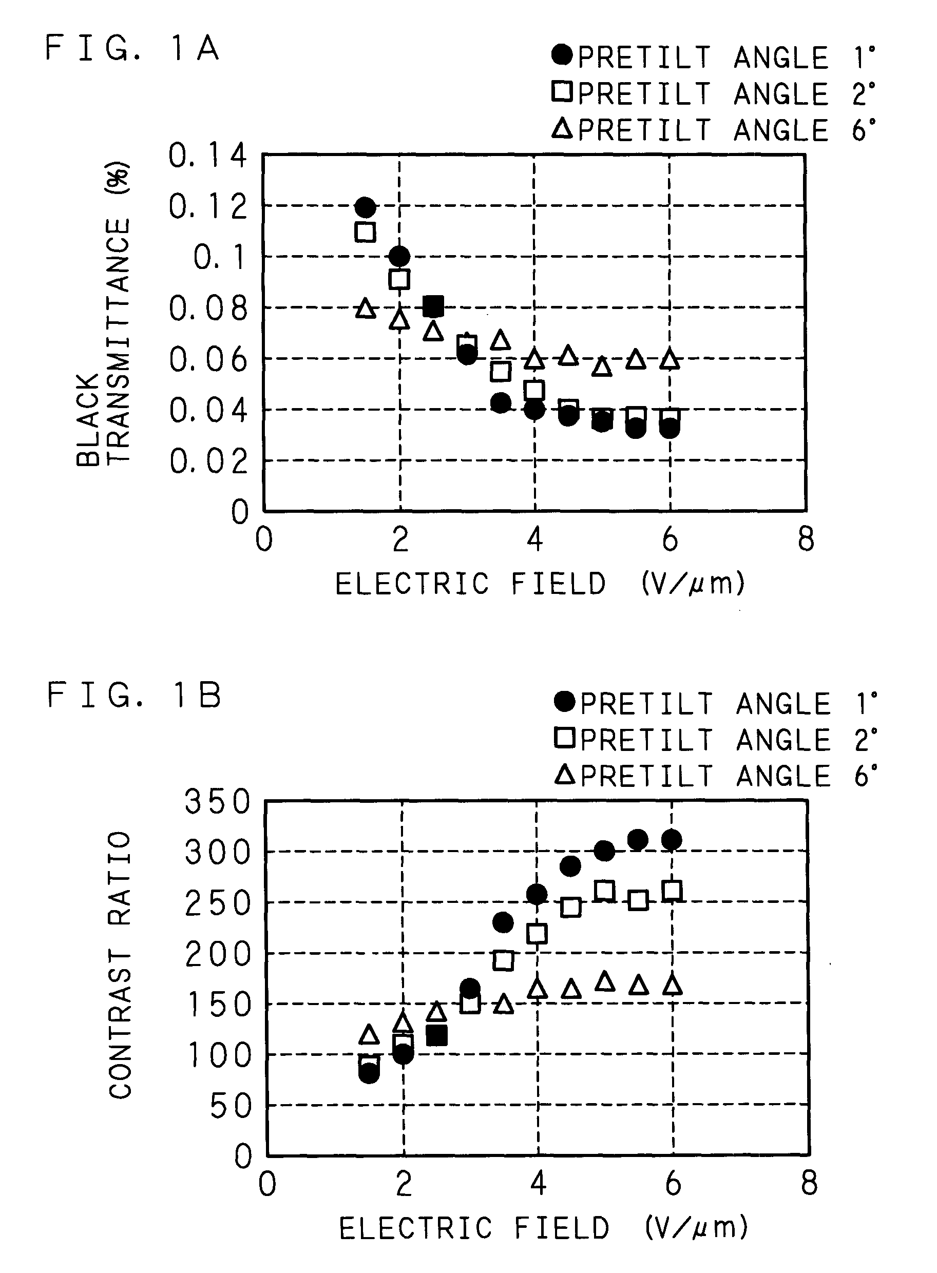
The conventional alignment treatment suffers from a problem that, despite the application of a DC voltage, uniform alignment of liquid crystal can not be obtained and a high contrast ratio can not be achieved.
It is considered that this problem is caused by other factors that dominate the alignment state of the liquid crystal.
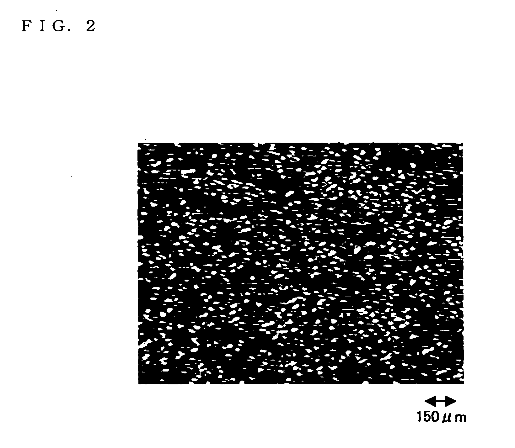
Black and white dots are present together, countless minute defects are seen, and a uniform black state is not obtained.
In short, it can be understood that the alignment treatment was not sufficient due to the low applied voltage in the alignment treatment, and a uniform alignment state was not obtained.

Method used


Image

  • Liquid crystal display device and manufacturing method of liquid crystal display device
  • Liquid crystal display device and manufacturing method of liquid crystal display device
  • Liquid crystal display device and manufacturing method of liquid crystal display device

Examples


embodiment 2

[0050] [Embodiment 2]

[0051] An empty panel with an electrode pattern different from that of Embodiment 1 was produced by the same method as in Embodiment 1. The basic specifications of the electrode pattern were 640.times.480 pixels and the electrode area of 6.times.10.sup.-5 cm.sup.2, and the size of the panel was 3.2 inches in diagonal. A TFT as a switching element was also formed for each pixel, and the pretilt angle was set only at 1.degree..

[0052] An evaluation panel (liquid crystal display device) was produced by introducing into the empty panel a liquid crystal showing the phase sequence: isotropic liquid (Iso) phase-cholesteric (Ch) phase-chiral smectic C (Sc*) phase from a high temperature side to a low temperature side. The transition temperature between the Iso phase and the Ch phase was 108.degree. C., the transition temperature between the Ch phase and the Sc* phase was 68.degree. C., and the magnitude of spontaneous polarization was 3.7 nC / cm.sup.2.

[0053] In the coolin...

embodiment 3

[0055] [Embodiment 3]

[0056] The following description will explain the present invention applied to a liquid crystal display device utilizing an active matrix driving scheme (active matrix liquid crystal display device, hereinafter referred to as TFT-LCD). Since the basic structures of the TFT-LCD as a liquid crystal display device are the same as those in Embodiment 1 and Embodiment 2, the major features are mainly explained. Note that, as a liquid crystal (monostable ferroelectric liquid crystal having spontaneous polarization), it is possible to use a liquid crystal showing the phase sequence: isotropic liquid (Iso) phase-cholesteric (Ch) phase (chiral nematic (N*) phase)-chiral smectic C (Sc*) phase, or a liquid crystal showing the phase sequence: isotropic liquid (Iso) phase-cholesteric (Ch) phase-smectic A (SA) phase-chiral smectic C (Sc*) phase, from a high temperature side to a low temperature side.

[0057] FIG. 6 is a structural view of a TFT-LCD, depicting the pixels arrange...

example 1 of embodiment 3

[0062] In Embodiment 3, in a temperature range in which the liquid crystal has a temperature between 73.degree. and 63.degree. (about 10 minutes at a cooling rate of 1.degree. / minute, the vicinity of the transition temperature from a higher temperature phase than chiral smectic C phase to the chiral smectic C phase) in the cooling process, a DC voltage of 5 V was applied to all the scanning lines (supply of a control voltage), a DC voltage of 4 V was applied to all the data lines (supply of a pixel voltage), and a voltage of 0 V was applied to the common electrode (common electrode line). Note that a pixel substrate potential equalizing line (Lds) for connecting the scanning lines and the data lines and a potential equalizing line between substrates (Ldsc) for connecting the pixel substrate potential equalizing line (Lds) and a common electrode line (Lc) are disconnected beforehand. Since the application of voltage as an alignment treatment is performed before installing (connecting...


PUM

PropertyMeasurementUnit
electric field strengthaaaaaaaaaa
electric fieldaaaaaaaaaa
pretilt angleaaaaaaaaaa

Abstract

The present invention provides a manufacturing method of a liquid crystal display device capable of achieving uniform alignment of monostable ferroelectric liquid crystal having spontaneous polarization, and provides the liquid crystal display device. The liquid crystal (monostable ferroelectric liquid crystal having spontaneous polarization) showing a phase sequence, either isotropic liquid phase-cholesteric phase-chiral smectic C phase, isotropic liquid phase-chiral nematic phase-chiral smectic C phase, or isotropic liquid phase-cholesteric phase-smectic A phase-chiral smectic C phase, from a high temperature side to a low temperature side, is sandwiched between two glass substrates having transparent electrodes and alignment films whose pretilt angle is not more than 2° and rubbing directions are parallel. In an alignment treatment which is performed to obtain a monostable state after heating the liquid crystal, an electric field with electric field strength of not less than 2 V/mum is applied in the vicinity of the transition temperature from a higher temperature phase than chiral smectic C phase to the chiral smectic C phase.

Description

[0001] The present invention relates to a manufacturing method of a liquid crystal display device and the liquid crystal display device, and more particularly relates to a manufacturing method of a liquid crystal display device using a liquid crystal having spontaneous polarization, and the liquid crystal display device.DESCRIPTION OF THE RELATED ART[0002] Along with the development of information-oriented society, small electronic apparatuses and mobile electronic apparatuses have been used. Accordingly, there is a demand for a small-size, light-weight, low-power consuming display unit for such electronic apparatuses, and then liquid crystal display devices that have superior characteristics compared to other display devices are in wide use.[0003] The liquid crystal display devices are mainly classified into a transmission type and a reflection type. From the viewpoint of visibility, transmission type liquid crystal display devices using a back-light are more widely adopted, and co...

Claims


Application Information

Patent Timeline
Patent Type & Authority Applications(United States)
IPC IPC(8): C09K19/02G02F1/137G02F1/133G02F1/1337G02F1/1368G02F1/139G02F1/141
CPCG02F1/141C09K19/0225G02F1/137
Inventor YOSHIHARA, TOSHIAKISHIROTO, HIRONORITADAKI, SHINJIMAKINO, TETSUYAKIYOTA, YOSHINORIKASAHARA, SHIGEOBETSUI, KEIICHI
Owner FUJITSU LTD
Why Eureka
Try Eureka