
Backlight device

a backlight device and liquid crystal technology, applied in static indicating devices, lighting and heating devices, instruments, etc., can solve the problems of shortening the life of each reflective type, poor visual identification, and unsuitable multicolor or full color displays in personal computers

Inactive Publication Date: 2004-03-04
TOKO KABUSHIKI KAISHA
View PDF5 Cites 40 Cited by
  • Summary
  • Abstract
  • Description
  • Claims
  • Application Information

AI Technical Summary

Problems solved by technology

However, the amount of reflected light varies according to environmental conditions, resulting in poor visual identification.
For this reason, reflective types are unsuitable as multicolor or full color displays in personal computers and the like.
Power Pr (=PL-Po) is obtained by subtracting the light-emission energy Po from the input power PL, and represents the heat loss in the LED; this heat loss shortens the life of each LED, and thermal destruction may reduce the brightness.

Method used

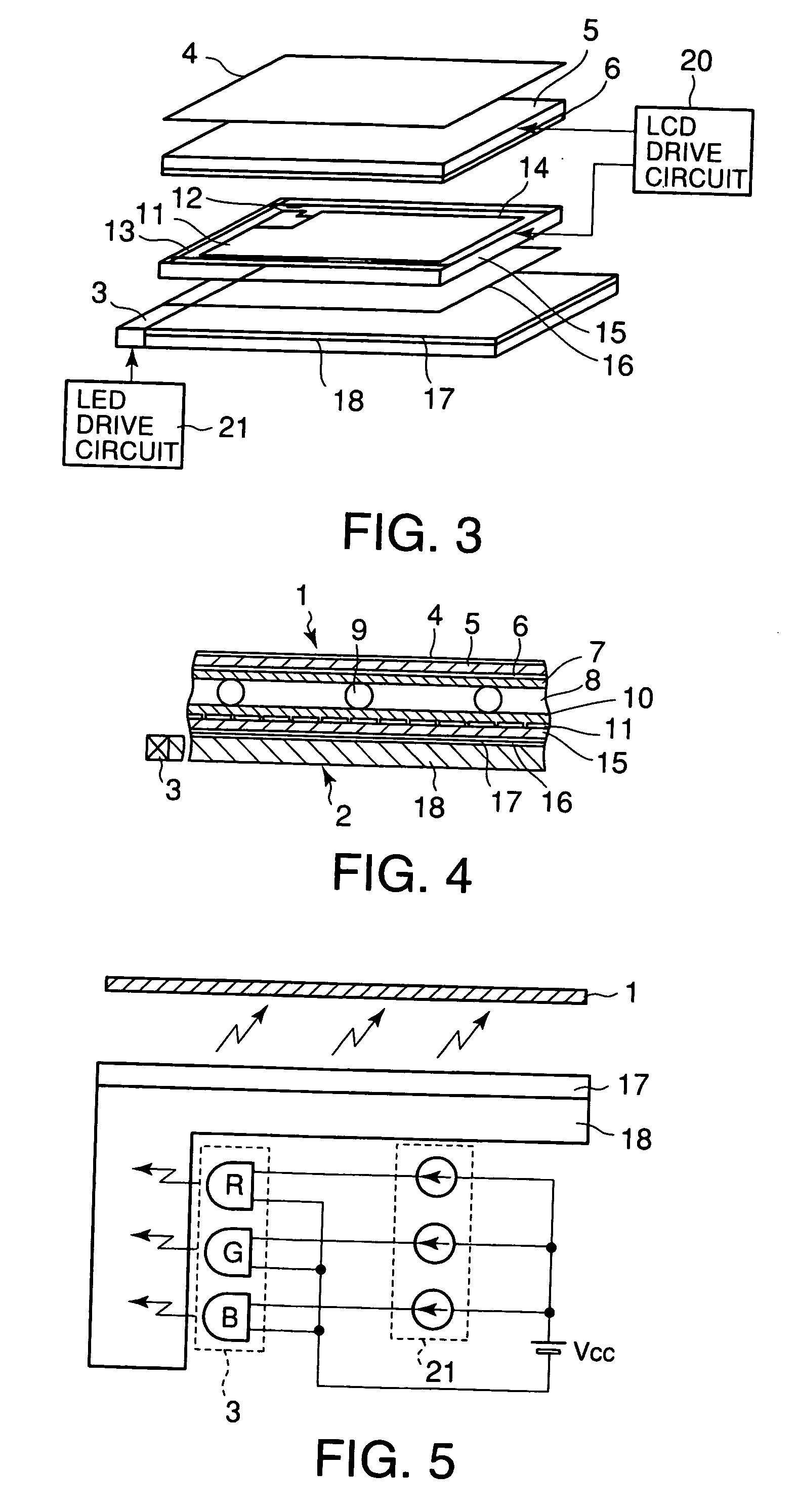

Image

  • Backlight device
  • Backlight device
  • Backlight device

Examples


Embodiment Construction

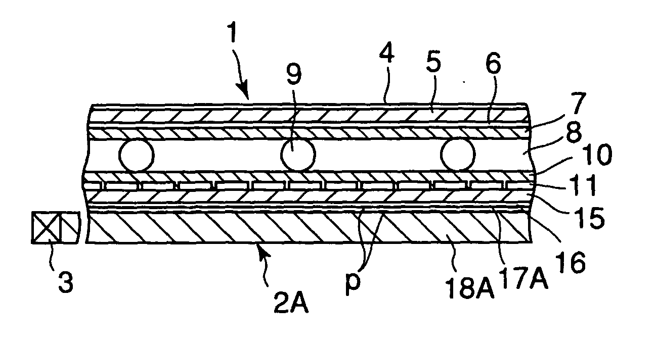
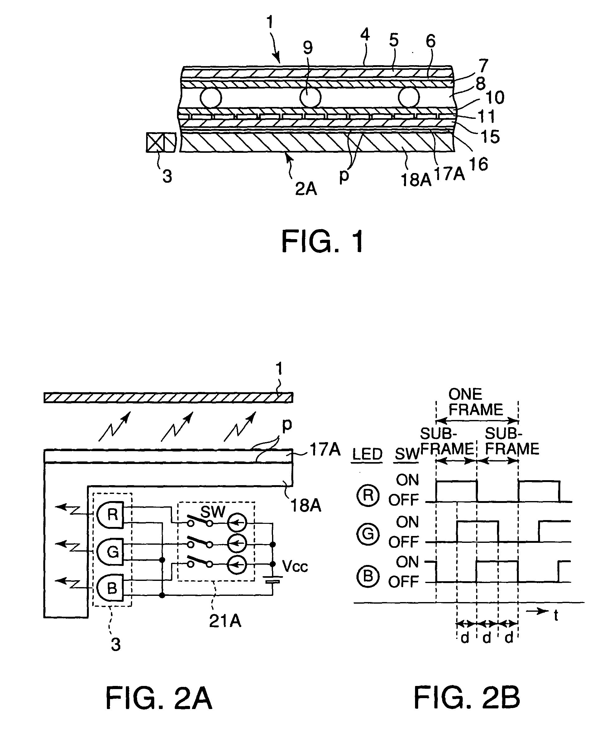
[0027] A backlight device according to an embodiment of this invention will be explained based on FIG. 1, FIG. 2A, and FIG. 2B.

[0028] FIG. 1 is a cross-sectional view of the constitution of a liquid crystal display device using the backlight device according to the embodiment of this invention.

[0029] As shown in FIG. 1, a light-polarizing plate 4, a glass substrate 5, a communal electrode 6, an alignment layer 7, a liquid crystal layer 8, a spacer 9, an alignment layer 10, a pixel electrode 11, a glass substrate 15 having a color filter, and a light-polarizing plate 16, are laminated sequentially from top to bottom, and together comprise a liquid crystal panel 1.

[0030] The backlight device 2A of this invention comprises phosphor p, provided on top of a light-scattering plate 17A and a light-conducting plate 18A, and an LED unit 3 and an unillustrated LED drive circuit. Parts, which are the same as those in FIGS. 3 and 4, are represented by the same reference codes.

[0031] FIG. 2A sho...


PUM


Abstract

A backlight device obtains white light by mixing and synthesizing the three primary colors, the white light appearing as bright to the human eye as conventional white light; in addition, the backlight device is highly economical, in that it reduces power consumption by reducing the effective power input to the light-emitting diodes, and lengthens the lives of the light-emitting diodes. In a backlight device comprising self-luminous-sources in the colors of red, green, and blue, the device mixing and synthesizing the three primary colors from the self-luminous sources into white light, in order to light a liquid crystal display device using a light-conducting plate and / or a light-scattering plate, the self-luminous-sources of the three primary colors are illuminated sequentially at different timings for each color, so that the light-generating timings partially overlap, achieving time-division light-emission.

Description

[0001] 1. Field of the Invention[0002] This invention relates to a liquid crystal display device, and more particularly relates to a backlight device, which is used for illuminating the liquid crystal display device, and provides a white light source comprised by mixing and synthesizing self-generated lights in the three primary colors.[0003] 2. Description of Related Art[0004] Recently, the proliferation of OA apparatuses, such as personal computers, has led to an increased need for portable OA apparatuses, which can be used in the office and outdoors, and increased demands to make such apparatuses smaller and lighter. A liquid crystal display device is widely used as one way of achieving these objects. Liquid crystal display devices can easily be made small and light, and are essential in reducing power consumption of battery-driven portable OA apparatuses.[0005] Liquid crystal display devices are broadly classified into reflective types and permeable types.[0006] In reflective ty...

Claims


Application Information

Patent Timeline
IPC IPC(8): F21V8/00G02F1/13357F21Y101/02G02F1/133H05B44/00
CPCG02B6/005G02B6/0068G02F1/133615H05B33/0857G02F2202/046H05B33/0818G02F2001/133622H05B45/20G02F1/133622
Inventor OTAKE, TETSUSHI
Owner TOKO KABUSHIKI KAISHA
Learn More