Opening flap, in particular flue gas escape flap, and opening mechanism therefor

a technology of opening mechanism and flap, which is applied in the field of opening flap, can solve the problems of unsuitable gas spring, unfavorable directions of force application, and unusual bulky design

Inactive Publication Date: 2004-03-04
SUSPA
View PDF0 Cites 17 Cited by
  • Summary
  • Abstract
  • Description
  • Claims
  • Application Information

AI Technical Summary

Benefits of technology

0007] According to the invention, this object is attained by the features which consist in that a double-armed lever is articulated to the lift arm by a pivot joint, to a first end, turned towards the principal energy accumulator, of which lever the secondary energy accumulator is articulated by its first end, and to a second end, turned towards the flap, of which lever is articulated a first end of a tie which is articulated by a second end relative to the frame. The measures according to the invention help attain that, at the beginning of the opening process when maximum load must be overcome, the principal gas spring exclusively or at least predominantly does the opening job, the secondary gas spring only serving as a forcing lever, transmitting the opening forces from the lift arm to the flap. The principal gas spring is completely extended only when the flap has been opened sufficiently far for a load of snow that might lie on it to have slipped off and any wind power has been o

Problems solved by technology

In the case of big flaps, it has been found that gas springs are not suitable.
DE 33 38 092 C3 describes a flap of the generic type, in which the additional energy accumulator is directly articulat

Method used


Image

  • Opening flap, in particular flue gas escape flap, and opening mechanism therefor
  • Opening flap, in particular flue gas escape flap, and opening mechanism therefor
  • Opening flap, in particular flue gas escape flap, and opening mechanism therefor

Examples


Embodiment Construction

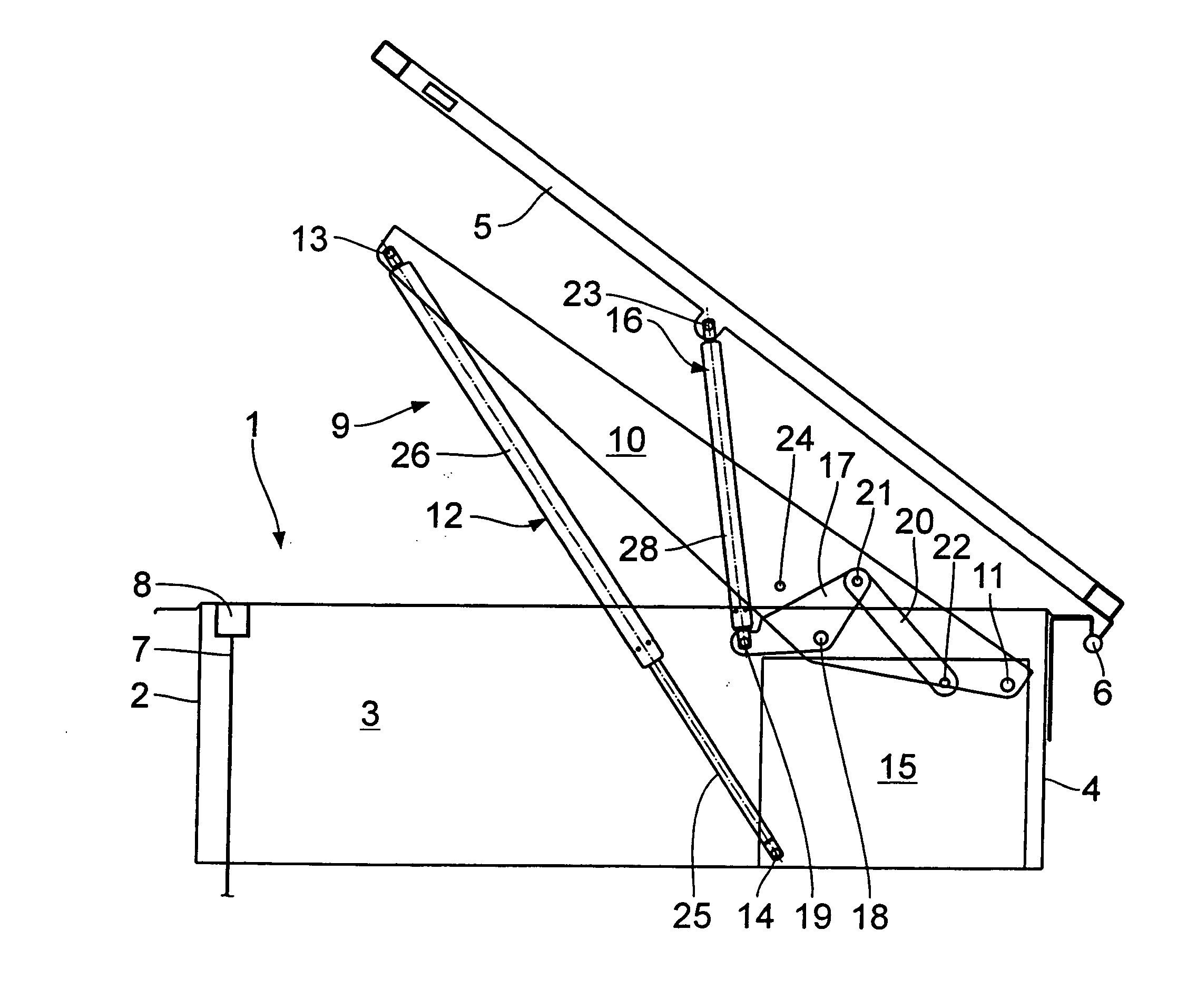
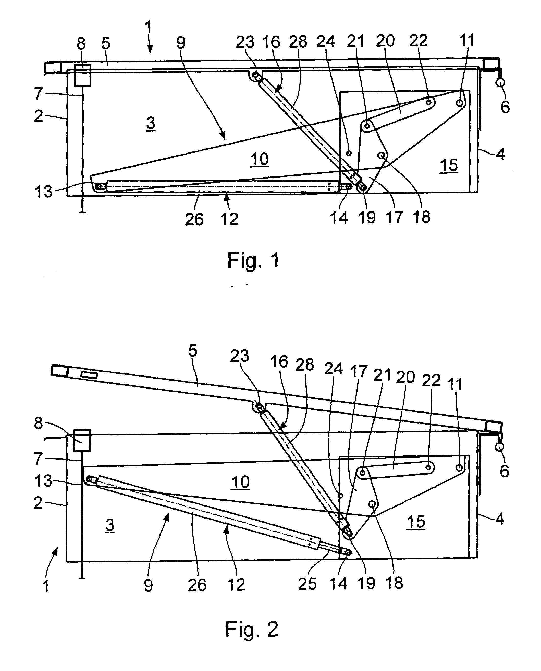
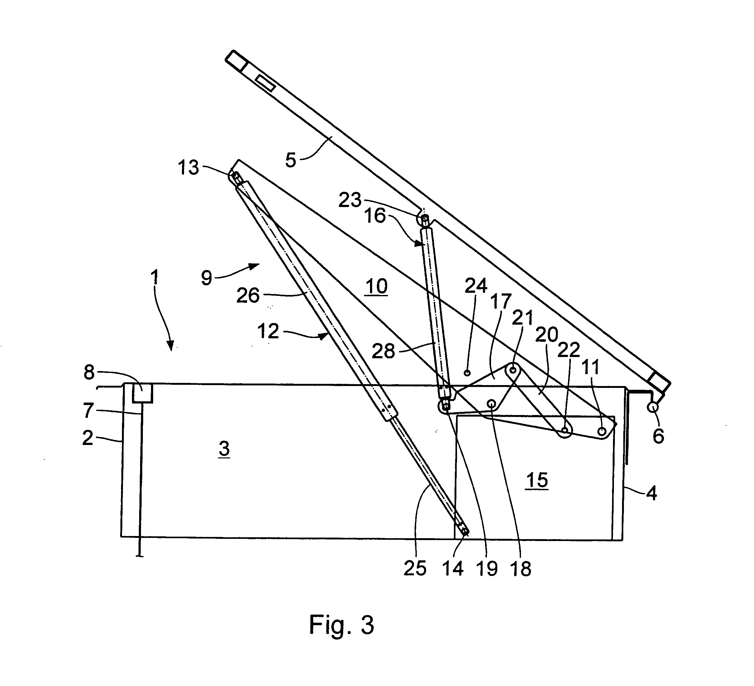
[0016] The roof-top skylight seen in the drawing works as a so-called flue gas escape flap mainly used in roofs of workshop halls. It has a frame 1 (roughly outlined) in the shape of a cuboid, which is open to the bottom and to the top, having a front wall 2, two side walls--only one side wall 3 of which is shown--and a rear wall 4. The flap 5, which may be designed as a window, is articulated to the upper edge of the rear wall 4 by means of a hinge 6 for it to pivot from a position of rest on the frame 1 into a position of opening by distinctly more than 90.degree., for example by approximately 140.degree., as seen in FIG. 5. The flap 5 is kept in the closed position by a rope 7 (roughly outlined), the holding device 8, by means of which the rope 7 is fixed to the flap in the vicinity of the front wall 2 of the frame 1, including a conventional safety fuse or the like which, in the case of fire, automatically disengages the rope 7 and the flap 5. Holding devices 8 and safety fuses ...


PUM


Abstract

An opening flap comprises a frame and a flap articulated thereto. A lift arm is provided, which is articulated by a principal energy accumulator. A secondary energy accumulator is articulated between the lift arm and the flap. The principal energy accumulator delivers the opening motion of the flap into a position before the dead center thereof. The secondary energy accumulator, which is distinctly weaker, delivers the subsequent opening motion.

Description

[0001] 1. Field of the Invention[0002] The invention relates to an opening flap, in particular flue gas escape flap, comprising a frame; a flap that is articulated to the frame; a holding device for keeping the flap in a closed position; a lift arm which is mounted for pivoting about a first joint that is stationary relative to the frame; a principal energy accumulator, a first end of which is articulated to a second joint that is stationary relative to the frame, and a second end of which is articulated to the lift arm by a third joint at a distance from the first joint; and a secondary energy accumulator, a first end of which is articulated to the lift arm between the first and the second joint, and a second end of which is articulated to the flap. The invention further relates to an opening mechanism for an opening flap according to the invention.[0003] 2. Background Art[0004] Flue gas escape flaps are employed predominantly for safety reasons in industrial buildings. They are su...

Claims


Application Information

Patent Timeline
IPC IPC(8): E04D13/035E05F1/00E05F1/10E05F15/20
CPCA62C2/248E04D13/0354E05F1/006E05F1/1091E05F15/72E05Y2201/422E05Y2800/244E05Y2900/154E05Y2800/22E05Y2201/416
Inventor RICHTER, STEFAN
Owner SUSPA
Why Eureka
Try Eureka