Device for cooling and heating a motor vehicle

Inactive Publication Date: 2004-03-18
ROBERT BOSCH GMBH
View PDF11 Cites 44 Cited by
  • Summary
  • Abstract
  • Description
  • Claims
  • Application Information

AI Technical Summary

Problems solved by technology

The need for cooling internal combustion engines arises from the fact that the surfaces contacted by the hot gases and their lubrication in the cylinder interiors can only withstand the attendant temperatures within certain limits without becoming damaged.
On the other hand, the significantly increased efficiency of modern engines, for example direct injecting diesel engines, places ever increasing limits on the amount of heat generated by the internal combustion engine that remains available for other uses in the cooling and heating system of the vehicle.
In some operating states of an engine, for example in the case of a cold start, when used for short trips, or even when the vehicle is traveling down long descents, the amount of heat input into the cooling water, which heat can be supplied by the engine itself, is no longer sufficient.
As a result, the engine and its catalytic converter

Method used


Image

  • Device for cooling and heating a motor vehicle
  • Device for cooling and heating a motor vehicle
  • Device for cooling and heating a motor vehicle

Examples


Embodiment Construction

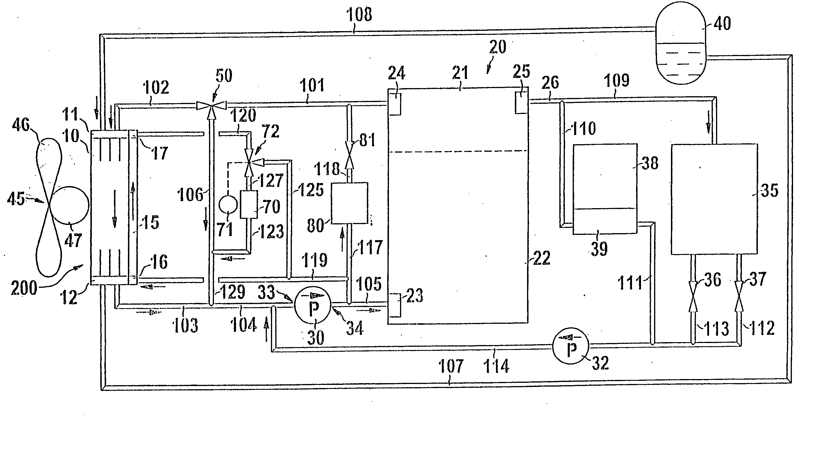
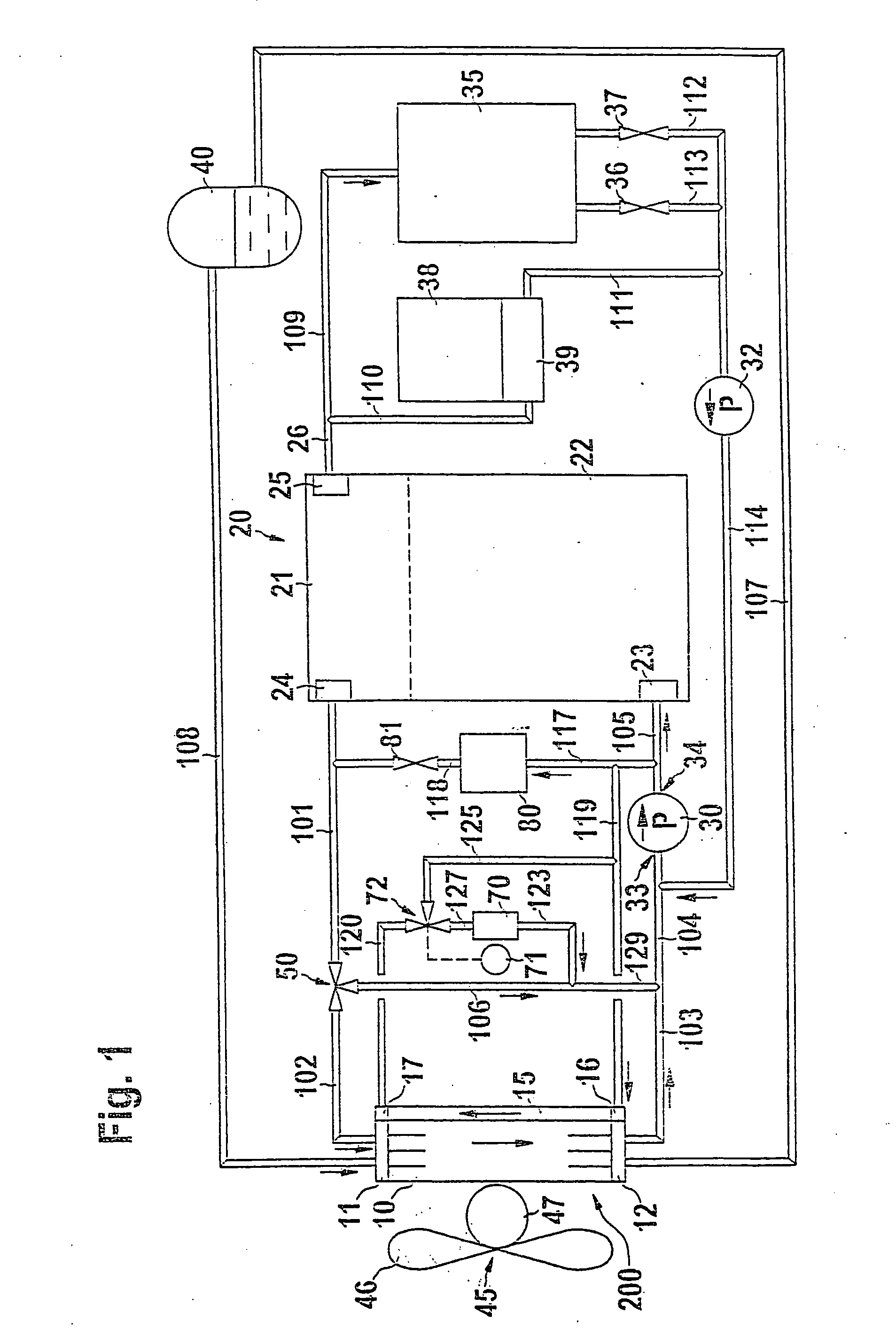
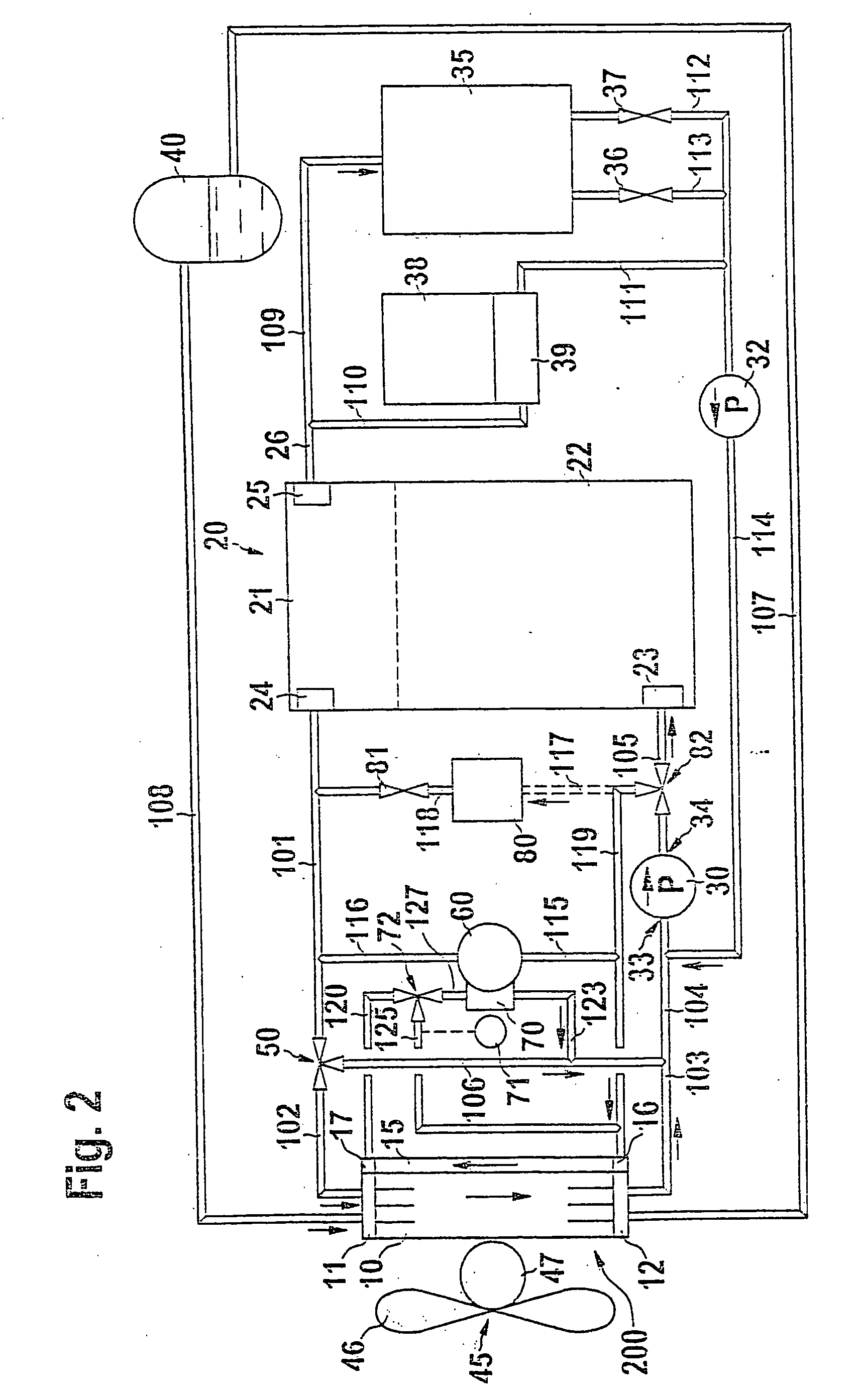
[0042] The first description will be of those components of the apparatus according to the invention for cooling and / or heating a motor vehicle, which are essentially the same for the embodiments according to FIGS. 1 to 3.

[0043] In the embodiments of the cooling system according to the invention shown in FIGS. 1 to 3, the apparatus includes a main cooler segment 10, which has a main cooler inlet 11 and a main cooler outlet 12. Adjacent to the main cooler segment 10, there is a cooling fan 45. The cooling fan 45 has a fan 46 and a fan motor 47. A compensation receptacle 40 is connected to the main cooler inlet 11 via a line section 108 and is connected to the main cooler outlet 12 via a line section 107.

[0044] The apparatus according to the invention, which is also referred to below in the same sense as a cooling system, serves primarily to cool an internal combustion engine 20. In a simplified representation, the engine 20 has a cylinder head 21 and an engine block 22. A coolant inl...


PUM


Abstract

The current invention relates to an apparatus for cooling and/or heating a motor vehicle, with at least one coolant pump (30, 32) for circulating a coolant in a cooling and heating system, with a main cooler segment (10), which has a main cooler inlet (11) and a main cooler outlet (12), wherein the main cooler inlet (11) is at least intermittently connected to at least one coolant outlet (24, 224, 225, 229) of an engine to be cooled (20), in particular an internal combustion engine, of the vehicle, and its main cooler outlet (12) is connected to at least one coolant inlet (23) of the engine (22), and with at least one other, secondary cooler segment (15, 215, 315, 415, 515) provided in addition to the main cooler segment (10) and at least one other unit to be cooled (60, 61, 70, 80, 90, 97, 170, 186), which is connected to the cooling and heating system. The invention proposes that the apparatus have at least one bypass line (125, 325) with a bypass valve (72, 251), which is associated with the at least one secondary cooler segment (15, 215, 315, 415, 515) and is disposed parallel to this secondary cooler segment (15, 215, 315, 415, 515) in the cooling and heating system of the motor vehicle.

Description

[0001] The current invention relates to an apparatus for cooling and / or heating a motor vehicle, according to the preamble of the independent claim.PRIOR ART[0002] The need for cooling internal combustion engines arises from the fact that the surfaces contacted by the hot gases and their lubrication in the cylinder interiors can only withstand the attendant temperatures within certain limits without becoming damaged. Individual parts such as sparkplugs, injectors, exhaust gas valves; prechambers, or even piston heads must be able to withstand particularly high average temperatures, which is why such parts must be made of materials with a high resistance to heat and with a favorable dissipation of heat and must be equipped with special cooling mechanisms. In order to achieve this dissipation of heat, cooling systems have therefore been developed, which contain a coolant that flows through the cooling water chambers that encompass at least the cylinders and cylinder heads, in order to...

Claims


Application Information

Patent Timeline
IPC IPC(8): F01P3/18F01P3/20F01P7/14F01P7/16
CPCF01P7/164F01P7/165F01P2003/187F01P2007/146F01P2023/08F01P2070/00F01P2050/30F01P2060/02F01P2060/08F01P2060/185F01P2050/24B60H1/00
Inventor HOHL, REINERSCHMITT, MANFREDMANN, KARSTENKAEFER, OLIVER
Owner ROBERT BOSCH GMBH
Why Eureka
Try Eureka