Apparatus and method of forming patch image for optimizing density control factor

a technology of density control factor which is applied in the field of image forming apparatus and image forming method, can solve the problems of difficult to set the density control factor to appropriate values, and it is difficult to correctly grasp the correlation between the density control factor and the image density, so as to achieve excellent image quality, suppress the influence of the density change of the patch image, and form stably toner image

Inactive Publication Date: 2004-03-25
SEIKO EPSON CORP
View PDF4 Cites 27 Cited by
  • Summary
  • Abstract
  • Description
  • Claims
  • Application Information

AI Technical Summary

Benefits of technology

[0009] A major object of the present invention is to provide an image forming apparatus and an image forming method according with which it is possible to suppress an influence of a density change of a patch image attributed to a variable factor which is related to a structure of the apparatus, and to stably form a toner image which has an excellent image quality.

Problems solved by technology

When an influence of such a density change is contained in a value which is detected as a patch image density, it is not possible to correctly grasp a correlation between the density control factors and an image density.
This further makes it difficult to set the density control factors to appropriate values even despite optimization of the density control factors based on patch image densities.
This may lead to a consequence that an image is formed under an image forming condition which is not an originally intended optimal condition.

Method used


Image

  • Apparatus and method of forming patch image for optimizing density control factor
  • Apparatus and method of forming patch image for optimizing density control factor
  • Apparatus and method of forming patch image for optimizing density control factor

Examples


first embodiment

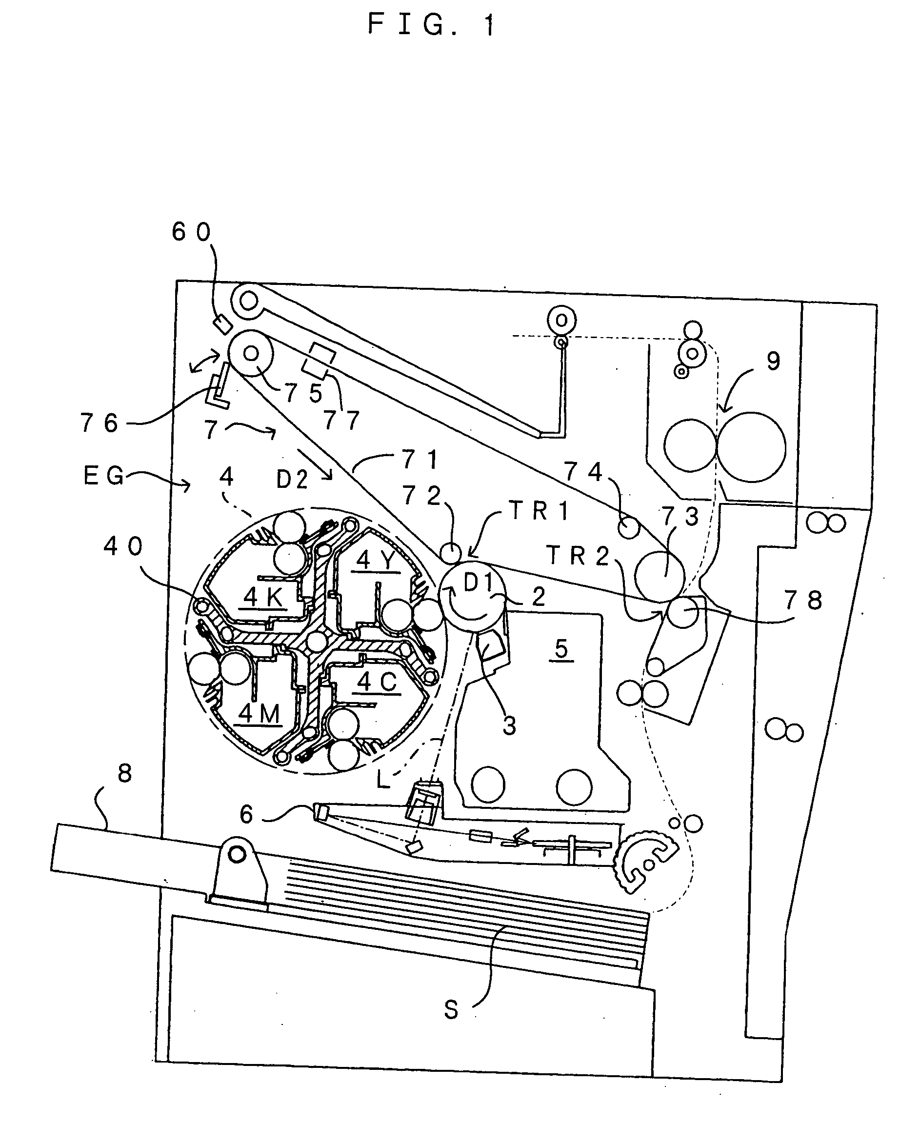
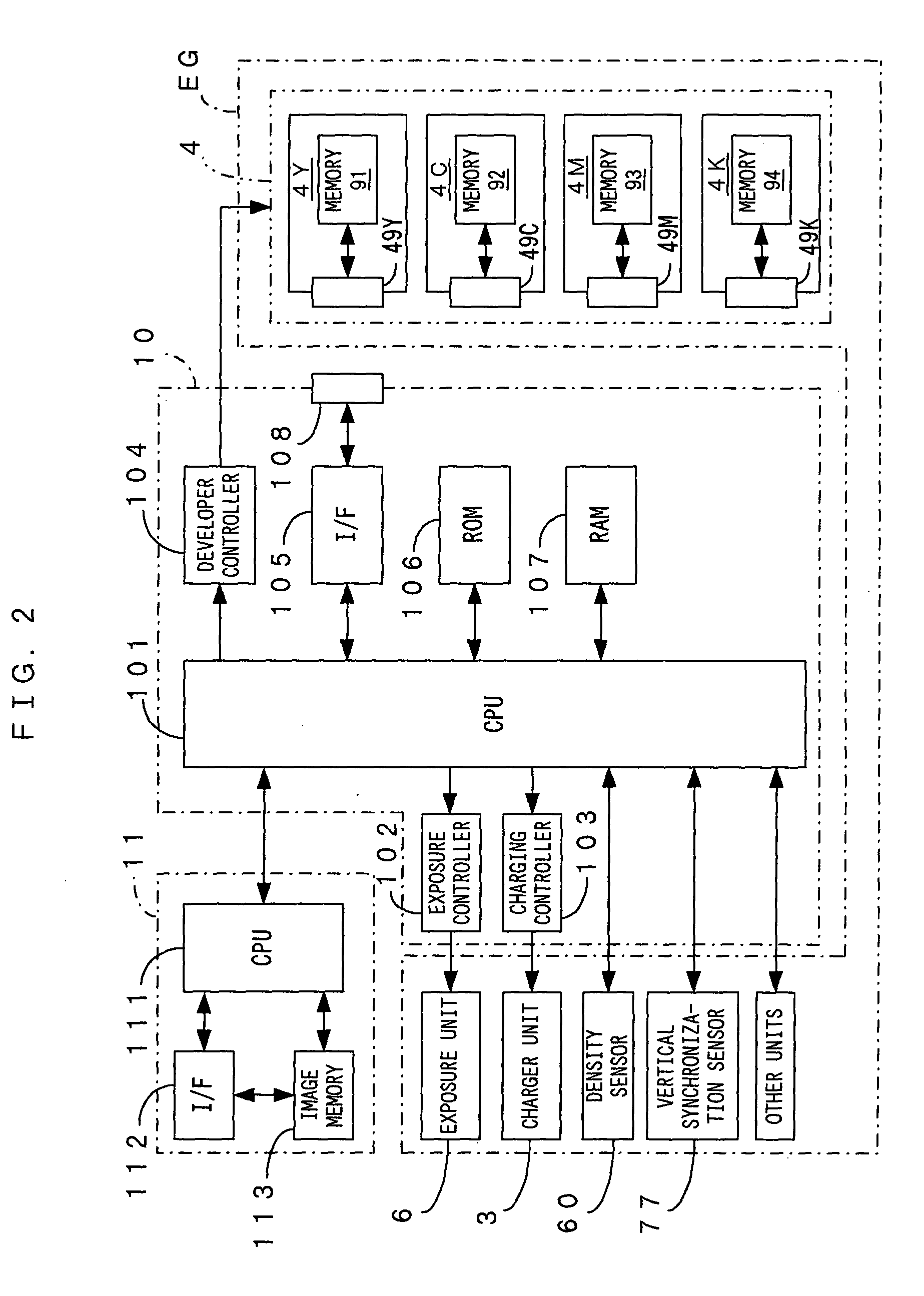
[0053] FIG. 1 is a drawing of an image forming apparatus according to the present invention. FIG. 2 is a block diagram of an electric structure of the image forming apparatus which is shown in FIG. 1. This image forming apparatus is an apparatus which superposes toner in four colors of yellow (Y), magenta (M), cyan (C) and black (K) and accordingly forms a full-color image, or uses only toner in black (K) and accordingly forms a monochrome image. In this image forming apparatus, when an image signal is fed to a main controller 11 from an external apparatus such as a host computer in response to an image formation request from a user, an engine controller 10 controls respective portions of an engine EG in accordance with an instruction received from the main controller 11 and an image which corresponds to the image signal is formed on a sheet S.

[0054] In the engine EG a photosensitive member 2 is disposed so that the photosensitive member 2 can freely rotate in the arrow direction D1...

first embodiment (

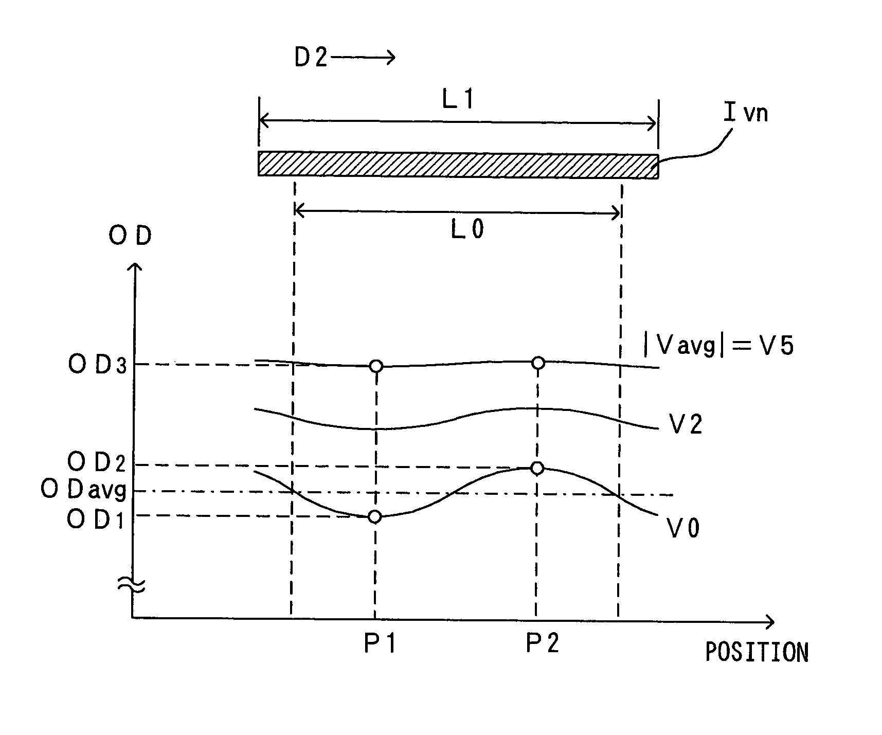
[0175] (III) First Embodiment (Cancellation of Influence Exerted by Photosensitive Member 2)

[0176] In the image forming apparatus shown in FIG. 1, a density of a patch image cyclically changes in accordance with the rotating cycles of the photosensitive member 2. And therefore, not only a density changes caused by a change in image forming condition (developing bias) but also a density change due to such a cyclic change are superimposed over a toner density of the patch image calculated from a result of detection executed on a local section of the rotating cycles. Hence, in some cases, a toner density calculated in this manner fails to correctly represent the density of the patch image under this image forming condition. Noting this, the first embodiment requires to calculate a toner density of a patch image under this image forming condition based on a result of detection executed on a length of the patch image which corresponds to the circumferential length of the photosensitive m...

fourth embodiment (

[0213] (V) Fourth Embodiment (Cancellation of Influence Exerted by Photosensitive Member 2 and Developer Roller 44)

[0214] In the image forming apparatus shown in FIG. 1, a density of a toner image developed at the developing position changes somewhat, depending on a variation of the structures or characteristics of the photosensitive member 2 and the developer roller 44, etc. Further, since these elements each rotate and move, a density of a toner image formed as a patch image shows a complex variation in accordance with variations of the structures or characteristics of the photosensitive member 2 and the developer roller 44 and the rotating cycles of these elements.

[0215] Noting this, in the fourth embodiment, influence exerted by the structure, the characteristics and the like of the photosensitive member 2 are separately extracted from influence exerted by structure, the characteristics and the like of the developer roller 44. In short, while density variations at the rotating c...


PUM


Abstract

For optimization of a direct current developing bias Vavg, a patch image Ivn is formed whose length is longer than a circumferential length L0 of a photosensitive member. From an average value of sensor outputs sampled over the length L0 of the patch image, a toner density of the patch image Ivn is calculated and a value corresponding to an average value ODavg of optical densities OD is accordingly found. This cancels an influence of density variations appearing in association with rotating cycles of the photosensitive member exerted over a patch image.

Description

BACKGROUND OF THE INVENTION[0001] 1. Field of the Invention[0002] The present invention relates to an image forming apparatus and an image forming method. In the apparatus, an electrostatic latent image is formed on an image carrier and toner moves to a surface of the image carrier from a toner carrier which carries the toner to thereby visualize the electrostatic latent image and form a toner image.[0003] 2. Description of the Related Art[0004] Known as image forming apparatuses, such as copier machines, printers and facsimile machines, to which electrophotographic techniques are applied are two types: those apparatuses of the contact developing type according to which an image carrier and a toner carrier are held abutting on each other; and those apparatuses of the non-contact developing type according to which an image carrier and a toner carrier are held away from each other. Of these, in an image forming apparatus of the contact developing type, a toner carrier is applied a dev...

Claims


Application Information

Patent Timeline
Patent Type & Authority Applications(United States)
IPC IPC(8): G03G15/00
CPCG03G15/5041G03G2215/00037
Inventor SHIMURA, HIDETSUGU
Owner SEIKO EPSON CORP
Why Eureka
Try Eureka