Integrated starter/generator for a turbomachine

Active Publication Date: 2004-04-15
SN DETUDE & DE CONSTR DE MOTEURS DAVIATION S N E C M A
View PDF10 Cites 94 Cited by
  • Summary
  • Abstract
  • Description
  • Claims
  • Application Information

AI Technical Summary

Benefits of technology

0024] The dispositions of the invention make it possible to envisage providing an aviation turbomachine in which the accessories are driven by electric motors powered by the electricity generators of the invention, and thus to eliminate the mechanical connections and the angle takeoffs, thereby reducing the weight of the engine and narrowing down

Problems solved by technology

The power takeoff system and the accessory housing have not been able to keep up with this progress and therefore represents an ever increasing proportion of the volume and the mass of engines, particularly low power engines that are of small size, and above all when the accessory housing, which is generally placed beneath or on the engine, and sometimes to one side of it, also contains an air starter and an electricity gener

Method used


Image

  • Integrated starter/generator for a turbomachine
  • Integrated starter/generator for a turbomachine
  • Integrated starter/generator for a turbomachine

Examples


Example

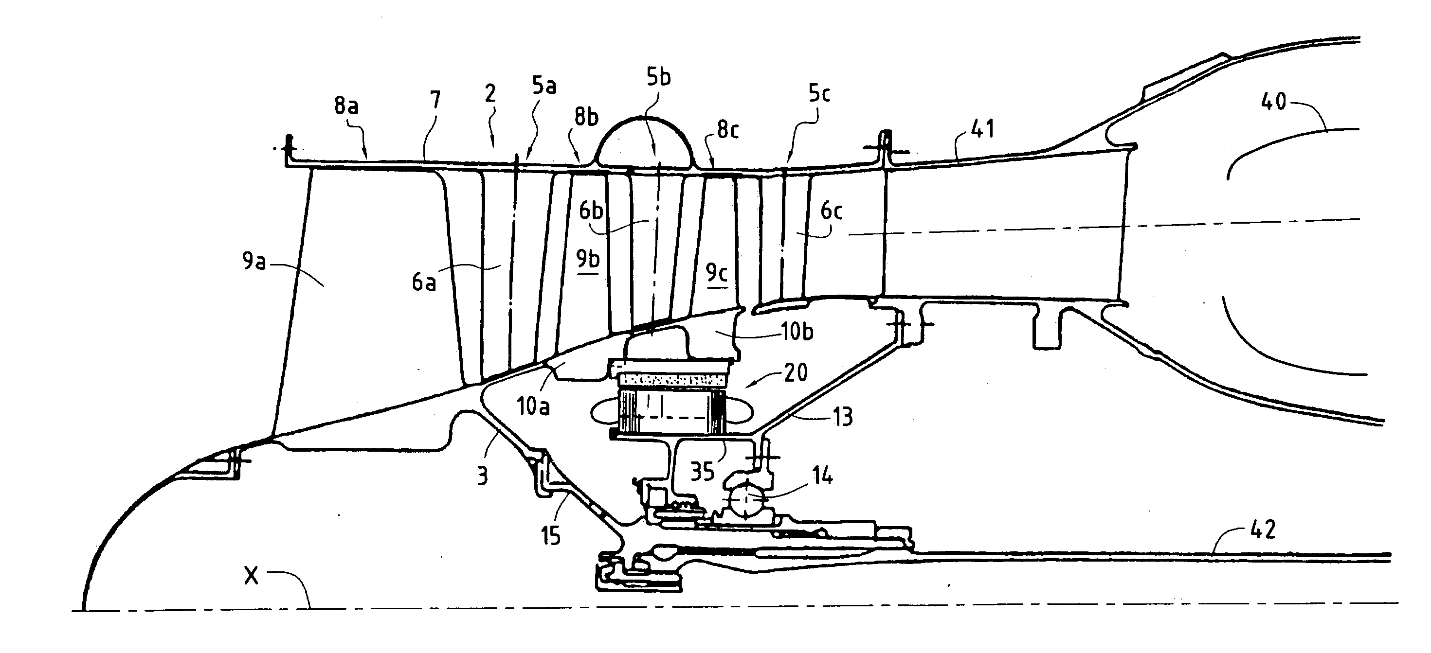
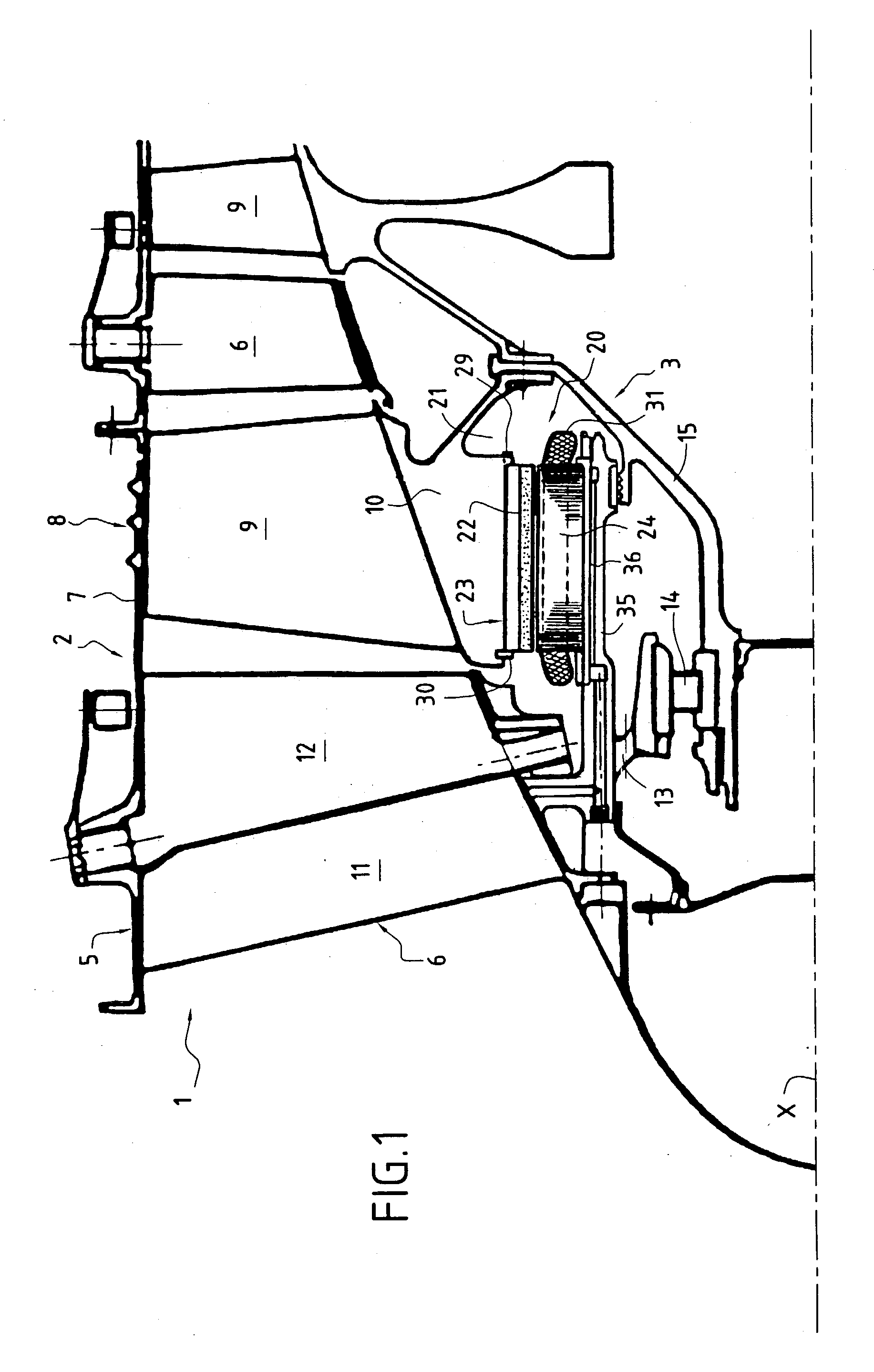
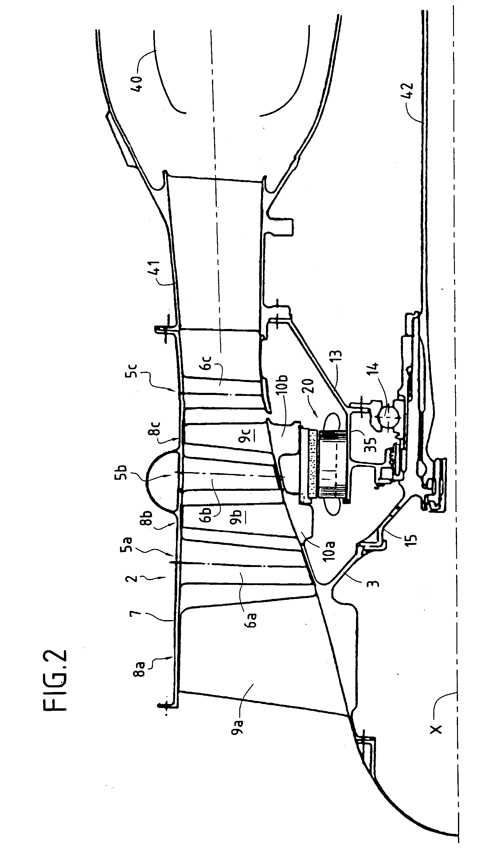
[0033] FIG. 1 shows the front portion of a single-shaft turbomachine 1 with an inlet casing and comprising, in front of the combustion chamber which is not in the drawing, an axial compressor 2 of axis X, whose rotor 3 is driven by the rotor of a turbine which transforms a fraction of the energy from the hot gas delivered by the combustion chamber into work compressing the air that penetrates into the compressor 2 from the front, said compressed air being delivered into the combustion chamber where fuel is injected and burnt. The other fraction of the energy from the gases coming from the combustion chamber serve to propel the aircraft fitted with said turbomachine.

[0034] The compressor has a plurality of compression stages. Each stage comprises a ring 5 of stationary blades 6 extending radially inwards from the outer casing 7 of the engine, and a ring 8 of moving blades 9 disposed downstream from the ring 5 of stationary blades 6, and which extend radially outwards from the periphe...


PUM


Abstract

The invention relates to a turbomachine of axis X including a compressor and an integrated starter/generator. The field magnetic circuit of the starter/generator is mounted in the bore of at least one disk of the compressor and surrounds the secondary magnetic circuit which is secured to a cylindrical shroud provided on the support structure for the bearing of the compressor. The invention applies in particular to single-shaft or multi-shaft turbomachines.

Description

[0001] The invention relates to a turbomachine for use in aviation, and more particularly to a turbomachine including an integrated electricity generator coaxial with the axis of the turbomachine.[0002] In a conventional engine, the accessory housing fitted with fuel pumps, oil pumps for lubricating bearings, hydraulic pumps for controlling various members, electricity generators, and the starter, is placed outside the engine and receives power taken from the engine by means of a vertical shaft and angle gearing.[0003] As time moves on, increasing compression ratios and turbine inlet temperatures, and also improvements in materials and in efficiency have led to the size of engines being constantly reduced so as to obtain ever greater thrust / weight ratios, and this applies both to civilian applications and to military applications.[0004] The power takeoff system and the accessory housing have not been able to keep up with this progress and therefore represents an ever increasing prop...

Claims


Application Information

Patent Timeline
IPC IPC(8): F01D15/10F02C7/268F02C7/32H02K7/14H02K7/18
CPCF01D15/10F02C7/268Y02T50/671H02K7/14H02K7/1823F02C7/32Y02T50/60
Inventor FRANCHET, MICHELPICARD, JEAN-LOUIS
Owner SN DETUDE & DE CONSTR DE MOTEURS DAVIATION S N E C M A
Why Eureka
Try Eureka