Light emitting diode based light source emitting collimated light

Inactive Publication Date: 2004-04-15
DOCUMENT SECURITY SYST
View PDF10 Cites 48 Cited by
  • Summary
  • Abstract
  • Description
  • Claims
  • Application Information

AI Technical Summary

Problems solved by technology

However, employment of a collimator with the light source 10 increases the manufacturing costs of devices incorporating one or more light sources 10.
Moreover, oper

Method used


Image

  • Light emitting diode based light source emitting collimated light
  • Light emitting diode based light source emitting collimated light
  • Light emitting diode based light source emitting collimated light

Examples


second embodiment

[0020] FIG. 4 illustrates the LED 22, which includes a bottom light absorbing layer 22d, a light reflecting layer 22e overlying the bottom light absorbing layer 22d, a light emitting layer 22f overlying the light reflecting layer 22e, and a top light absorbing layer 22g overlying the light emitting layer 22f. Due to the light absorbing nature of the light absorbing layers 22d and 22g and the light reflecting nature of the light reflecting layer 22e, the illustrated LED emits light exclusively from the side surfaces of the light emitting layer 22f as exemplified by the dashed arrows.

third embodiment

[0021] FIG. 5 illustrates the LED 22, which includes a bottom light absorbing layer 22h, a light reflecting layer 22i overlying the bottom light absorbing layer 22h, a light emitting layer 22j overlying the light reflecting layer 22i, and a top light reflecting layer 22k overlying the light emitting layer 22j. Due to the light absorbing nature of the light absorbing layer 22h and the light reflecting nature of the light reflecting layers 22i and 22k, the illustrated LED emits light exclusively from the side surfaces of the light emitting layer 22j as exemplified by the dashed arrows.

fourth embodiment

[0022] FIG. 6 illustrates the LED 22, which includes a bottom light absorbing layer 22l, a light emitting layer 22m overlying the bottom light absorbing layer 22l, a light transmitting layer 22n overlying the light emitting layer 22m, and a top light reflecting layer 22o overlying the light transmitting layer 22n. Due to the light absorbing nature of the light absorbing layer 221 and the light reflecting nature of the light reflecting layer 22o, the illustrated LED emits light exclusively from the side surfaces of the light emitting layer 22m and the light transmitting layer 22n as exemplified by the dashed arrows.


PUM


Abstract

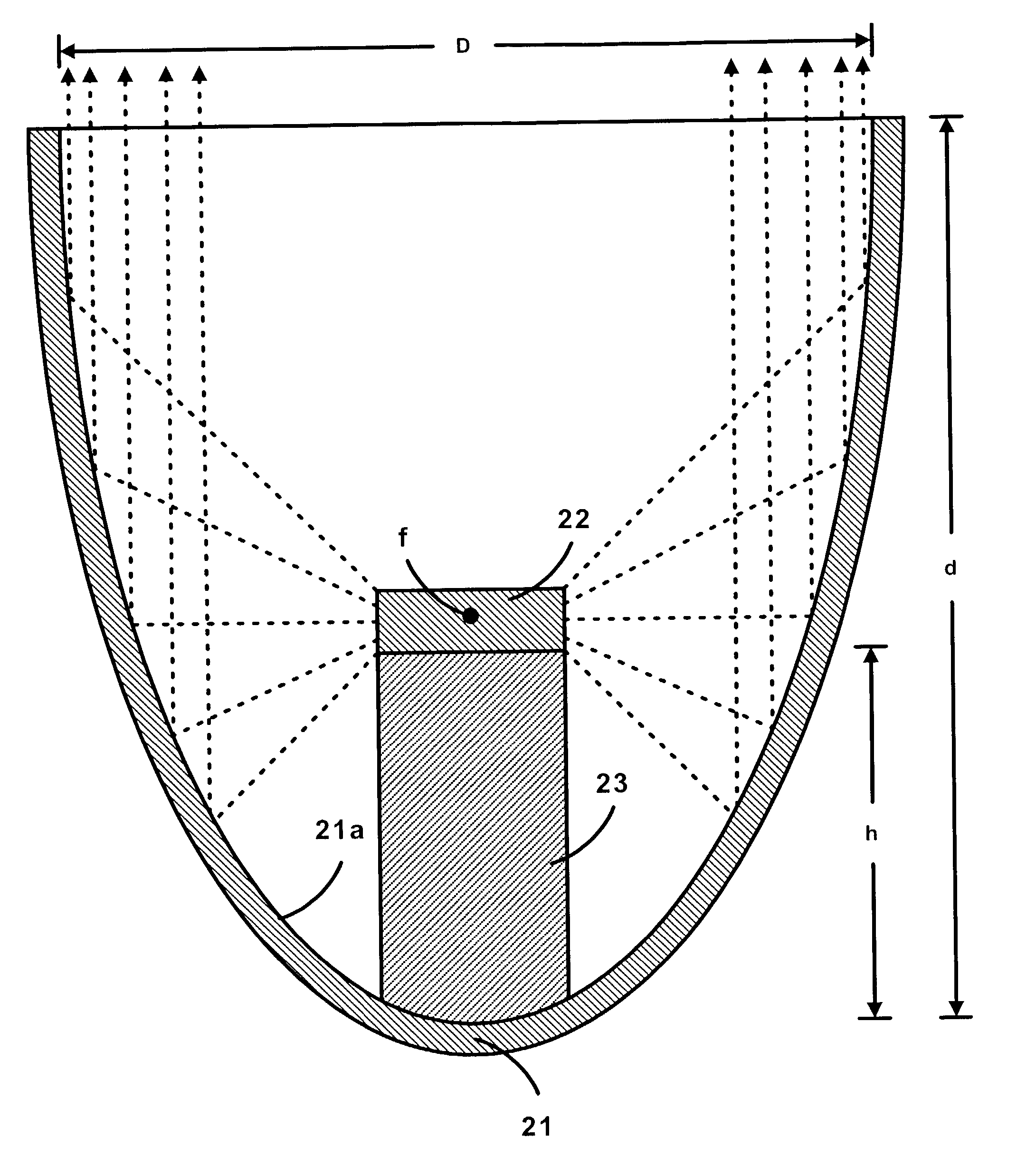
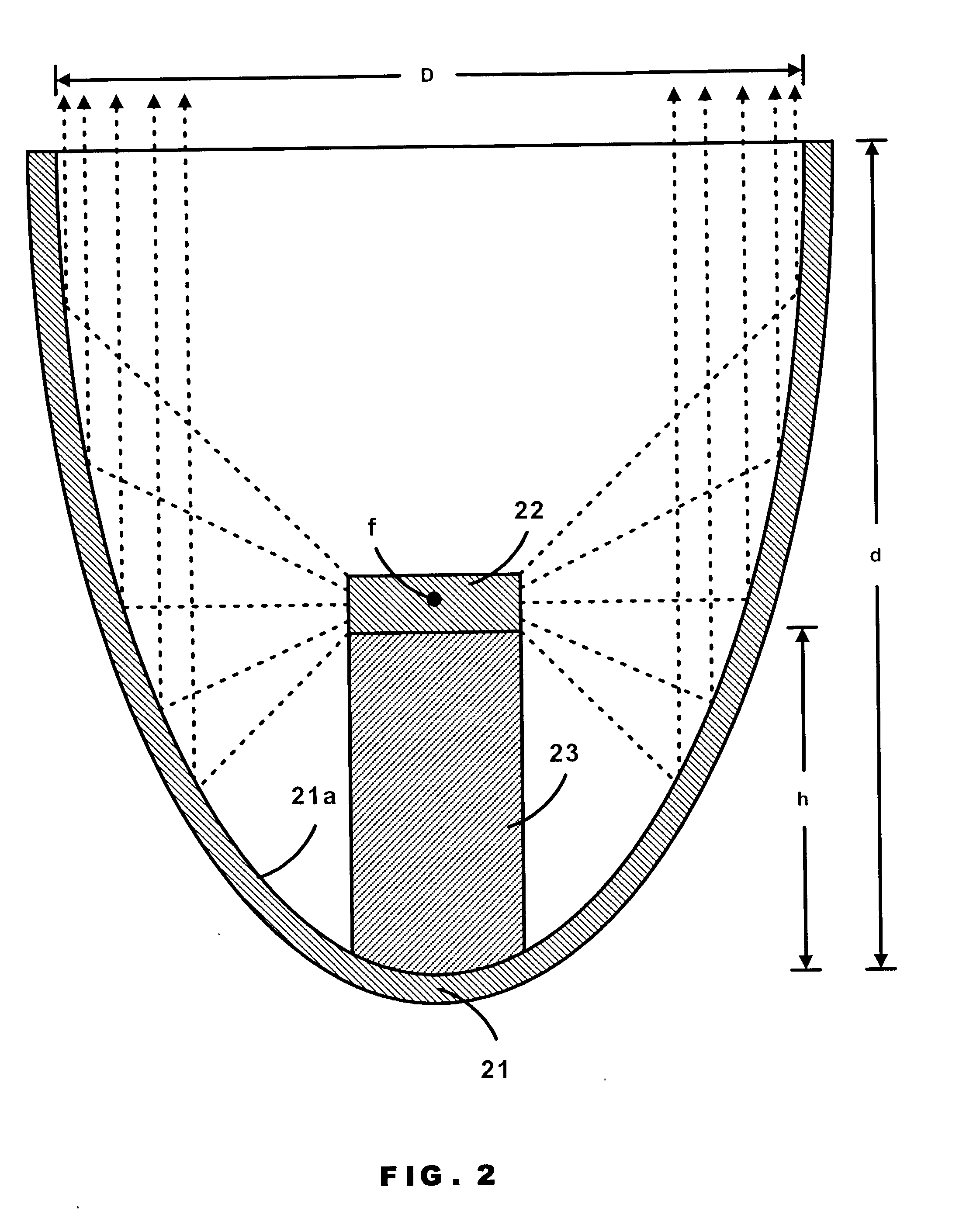
A light emitting diode, a reflector and a platform are employed within a light source. The light emitting diode emits light exclusively from its side surfaces. The reflector has a parabolic reflective surface that collimates any portion of the light reflecting from the parabolic reflective surface. The platform supports a centering of the light emitting layer(s) of the light emitting diode on a focus point of the parabolic reflective surface.

Description

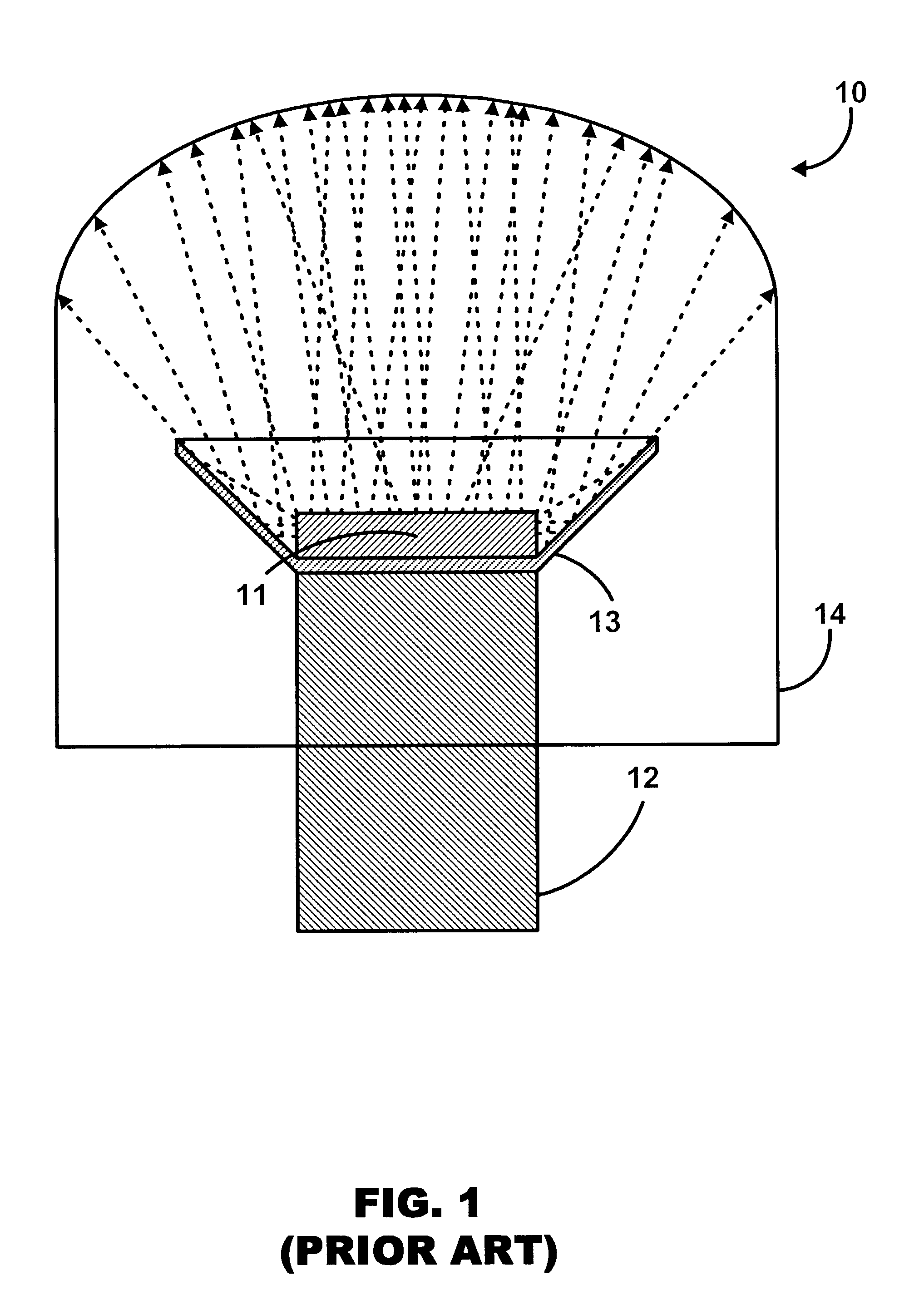
[0001] The present invention generally relates to the field of light sources. More specifically, the present invention relates to a Light Emitting Diode ("LED") based light source that is independently operative to emit a collimated light.DESCRIPTION OF THE RELATED ART[0002] FIG. 1 illustrates a known light source 10 having a LED 11 positioned on an electrical connector 12 to thereby emit light from its top surface and side surfaces as exemplified by the dashed arrows. The reflector 13 has a conical reflective surface serving the known function of reflecting the light emitted from the LED 11 in the direction of the conical reflective surface. A dome 14 serves the known function of focusing the light reflected from the conical reflective surface of the reflector 13 into an operational radiation pattern as the light leaves the dome 14. As illustrated, neither the reflector 13 nor the dome 14 collimates the light reflected from the conical reflective surface of the reflector 13. The li...

Claims


Application Information

Patent Timeline
IPC IPC(8): H01L33/44H01L33/46H01L33/60
CPCH01L33/44Y10S362/80H01L33/60H01L33/46
Inventor GOH, KEE SIANGLEE, BOON KHENGCHIN, YEE LOONGSINGH, GURBIR
Owner DOCUMENT SECURITY SYST
Why Eureka
Try Eureka