
Vehicle headlamp

a headlamp and vehicle technology, applied in vehicle headlamps, transportation and packaging, light and heating equipment, etc., to achieve the effect of reducing weight, and reducing the number of components

Active Publication Date: 2010-07-01
ICHIKOH IND LTD
View PDF16 Cites 44 Cited by
  • Summary
  • Abstract
  • Description
  • Claims
  • Application Information

AI Technical Summary

Benefits of technology

[0053]In addition, the vehicle headlamp according to the first aspect of the present invention is made of: the main reflector having the convergent reflecting surface; the semiconductor-type light source; the projecting lens; the auxiliary reflector having the parabolic reflecting surface; the shade: the light shading member; and the switching device. Therefore, in comparison with the conventional vehicle headlamp, the number of components is reduced without requiring the second light source unit for high-beam light distribution pattern; and downsizing, weight reduction, and cost reduction can be achieved accordingly.
[0054]Moreover, the vehicle headlamp according to the first aspect of the present invention utilizes the reflected convergent light that has been cut off by means of the shade so far, to thereby form the basic light distribution of the light distribution pattern for high beam. This headlamp also effectively utilizes the radiated light from the semiconductor-type light source, which is disallowed to be targeted for light distribution on the convergent reflecting surface by means of the parabola reflecting surface of the auxiliary reflector, to thereby form the spot light distribution of the light distribution pattern for high beam. As a result, the vehicle headlamp according to the first aspect of the present invention is capable of obtaining the light distribution pattern for high beam with its superior distant visibility. This headlamp is also capable of obtaining the sense of moderation in switching between the light distribution pattern for low beam, having the cutoff lines, and the light distribution pattern for high beam.
[0056]Further, the vehicle headlamp according to the third aspect of the present invention is provided in such a manner that: by integrally structuring the shade and the light shading member with each other, the number of components can be further reduced; and moreover, the switching device for switching the shade and the light shading member to each other can be used all together. Therefore, the number of components can be further reduced, and downsizing, weight reduction, power saving, and cost reduction can be achieved accordingly.
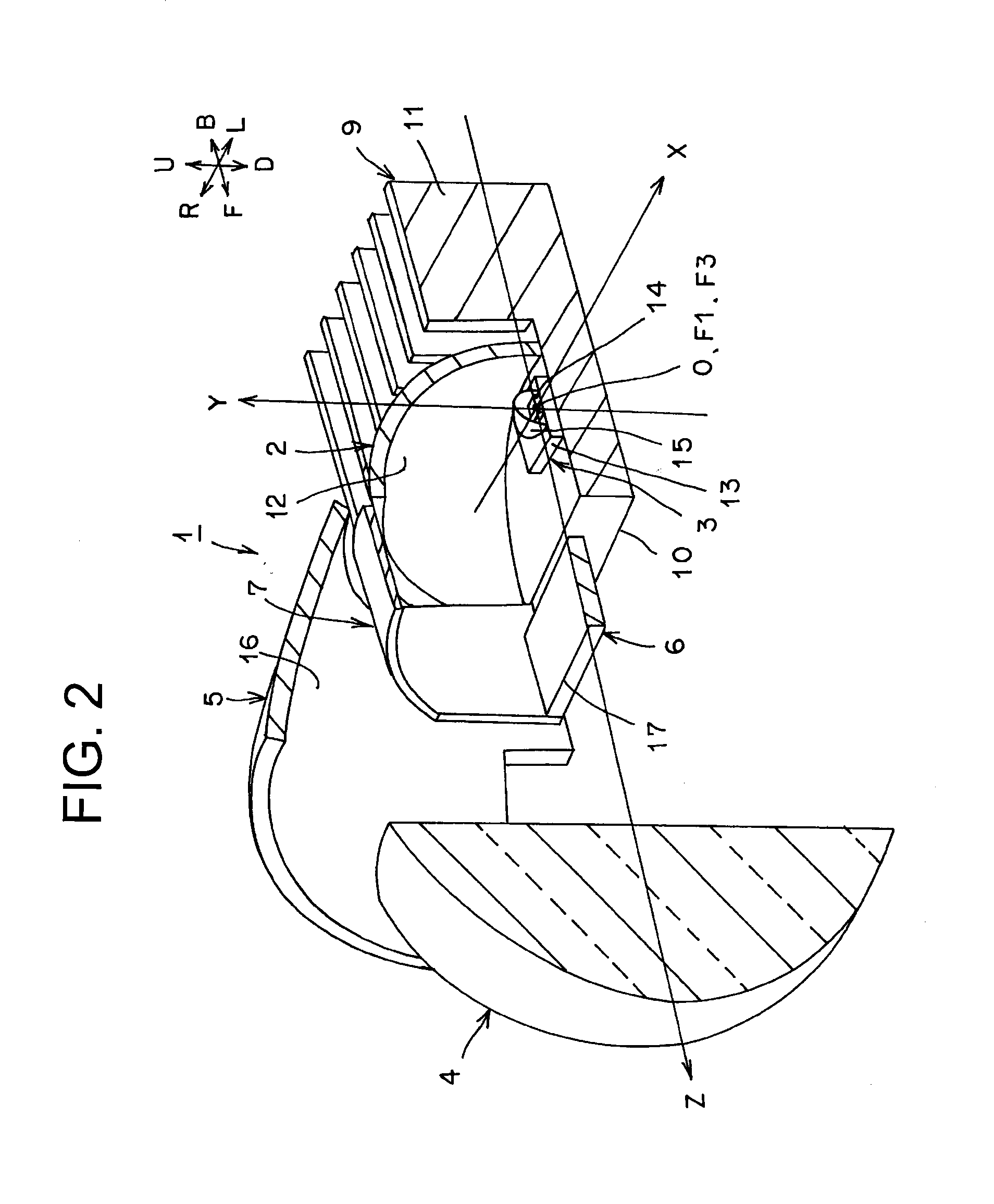
[0057]Moreover, the vehicle headlamp according to the third aspect of the present invention allows the shade and light shading member, which are structured integrally with each other, to be disposed to be rotationally movable between the first location and the second location in a backside location (the location close to the first focal point of the convergent reflecting surface), with respect to the Z-axis direction from the second focal point (lens focal point of the projecting lens) of the convergent reflecting surface. Thus, even if a rotational angle is small between the shade and the light shading member, which are structured integrally with each other, the rotational movement quantity increases at a portion at the side of the second focal point (lens focal point of the projector lens) of the convergent reflecting surface of the shade, namely at a portion of the edge forming the cutoff lines of the light distribution pattern for low beam. As a result, the vehicle headlamp according to the third aspect of the present invention is provided in such a manner that, even if the shade is rotated at a small rotational angle, the reflected convergent light is allowed to be reliably cut off or pass through the projector lens without being cut off. In this manner, the vehicle headlamp according to the third aspect of the present invention makes compact and inexpensive the switching device for rotating the shade and light shading member, which are structured integrally with each other; and therefore, downsizing and cost reduction can be achieved accordingly.

Problems solved by technology

Thus, the conventional vehicle headlamp requires a large number of components and the second light source unit for a light distribution pattern for high beam, and entails problems concerning downsizing, weight reduction, power saving, and cost reduction, accordingly.

Method used


Image

  • Vehicle headlamp
  • Vehicle headlamp
  • Vehicle headlamp

Examples


embodiment

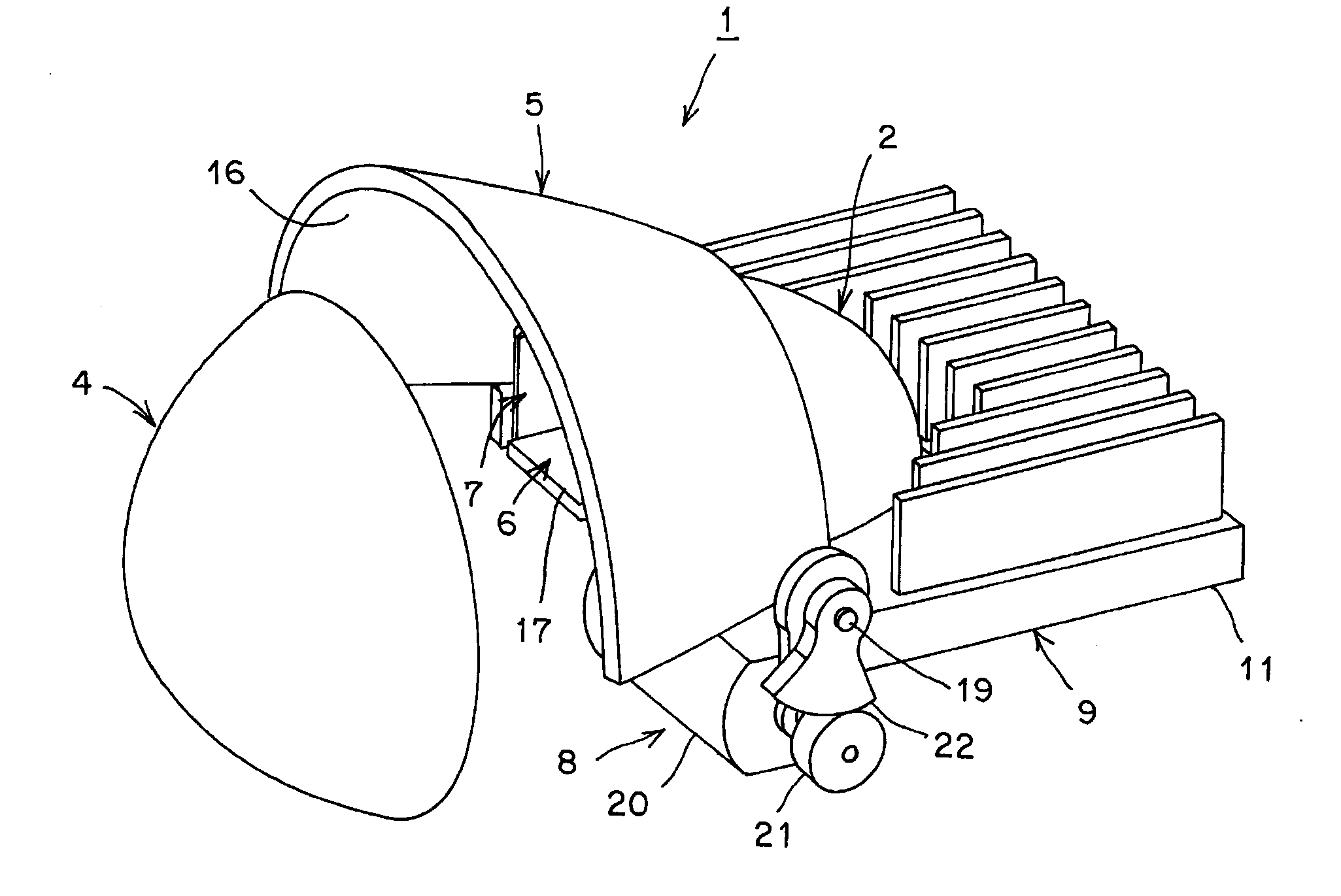
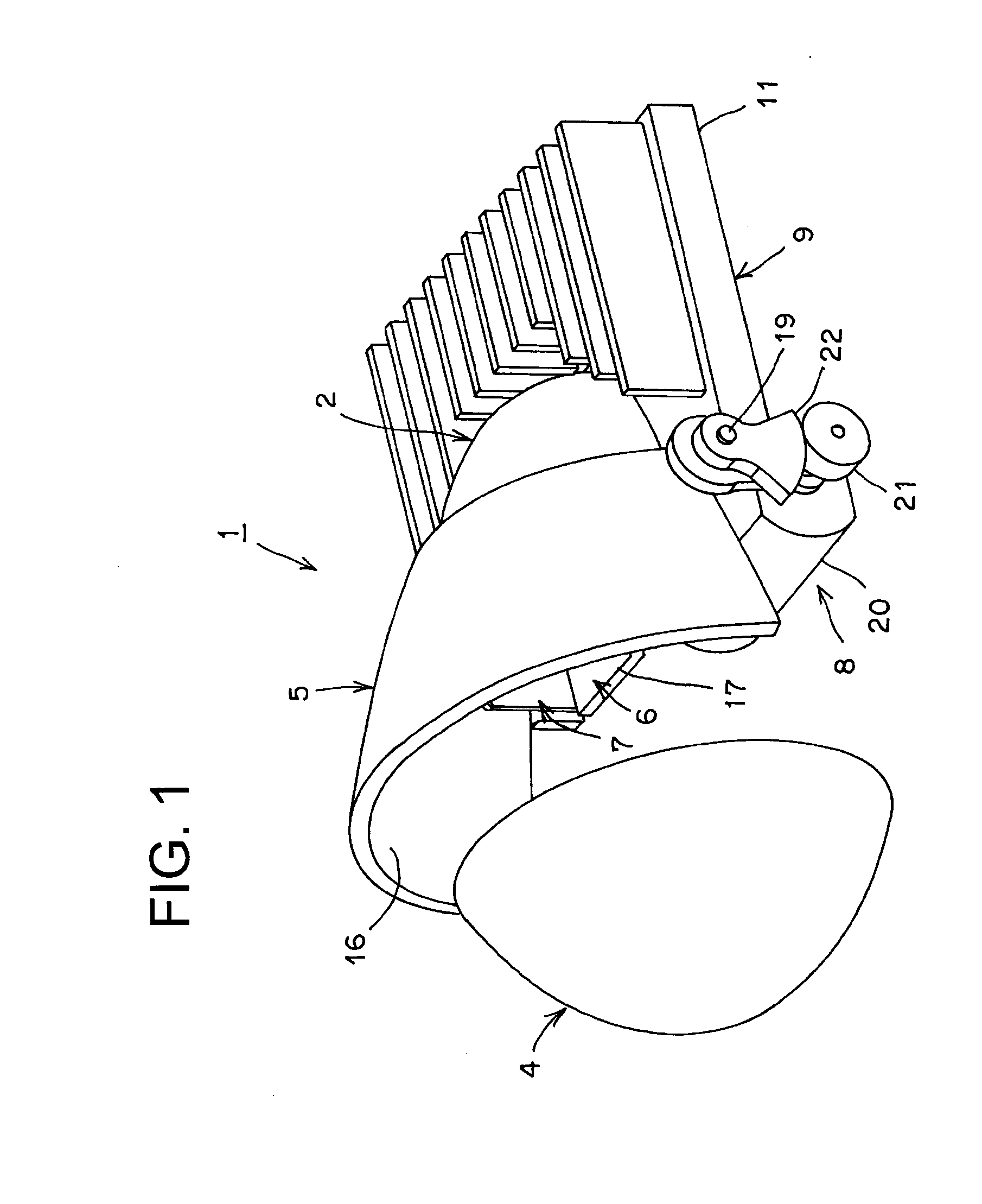
[0068]Hereinafter, a constitution of the vehicle headlamp of the first embodiment will be described. In the figures, reference numeral 1 designates a vehicle headlamp (automobile headlamp) of the first embodiment. The vehicle headlamp 1 is a vehicle headlamp for left-side cruising lane. A vehicle headlamp for right-side cruising lane is transversely reversed in the vehicle headlamp 1 for left-side cruising lane. In addition, in FIG. 2, the X, Y, and Z axes constitute an orthogonal coordinate system (X-Y-Z orthogonal coordinate system). The X axis corresponds to a leftward-rightward horizontal axis and a cruising lane side. In other words, in the first embodiment, the left side L corresponds to a positive direction and the right side R corresponds to a negative direction. In addition, the Y axis corresponds to an upside-downside vertical axis, and in the first embodiment, the upside U corresponds to a positive direction and the downside D corresponds to a negative direction. Further,...


PUM


Abstract

A vehicle headlamp is provided with: a main reflector having a convergent reflecting surface; a semiconductor-type light source; a projecting lens; an auxiliary reflector having a parabolic reflecting surface; a shade and a light shading member that are structured integrally with each other; and a switching device. By means of the switching device, the shade and light shading member, which are structured integrally with each other, are switched and positioned in a first location and a second location, thereby allowing light distribution patterns for high and low beams to be switched and illuminated toward a forward direction of a vehicle. As a result, the vehicle headlamp becomes capable of achieving downsizing, weight reduction, power saving, and cost reduction.

Description

CROSS-REFERENCE TO RELATED APPLICATIONS[0001]This application claims priority of Japanese Patent Application No. 2008-333183 filed on Dec. 26, 2008. The contents of this application are incorporated herein by reference in their entirety.BACKGROUND OF THE INVENTION[0002]1. Field of the Invention[0003]The present invention relates to a vehicle headlamp of a projector type, employing a semiconductor-type light source to illuminate light to a forward direction of a vehicle by switching a light distribution pattern having one or more cutoff lines (light distribution pattern for low beam, light distribution pattern for passing) and a light distribution pattern for high beam (light distribution pattern for cruising).[0004]2. Description of the Related Art[0005]A vehicle headlamp of this type is conventionally known (Japanese Laid-open Patent Application No 2007-109493, for example). Hereinafter, a conventional vehicle headlamp will be described. The conventional vehicle headlamp is made up...

Claims


Application Information

Patent Timeline
Patent Type & Authority Applications(United States)
IPC IPC(8): B60Q1/04
CPCF21S41/147F21S41/155F21W2102/00F21S41/689F21S41/43F21S41/148F21W2102/14F21W2102/30
Inventor OKUBO, YASUHIROABE, TOSHIYA
Owner ICHIKOH IND LTD
Learn More