
Photovoltaic generator with a spherical imaging lens for use with a paraboloidal solar reflector

a photovoltaic generator and paraboloidal technology, applied in the direction of heat collector mounting/support, manufacturing tools, light and heating equipment, etc., can solve the problems of low efficiency, achieve low parasitic power loss for the coolant pump and fan of the active cooling system, and increase the surface area

Active Publication Date: 2009-11-12
THE ARIZONA BOARD OF REGENTS ON BEHALF OF THE UNIV OF ARIZONA
View PDF39 Cites 48 Cited by
  • Summary
  • Abstract
  • Description
  • Claims
  • Application Information

AI Technical Summary

Benefits of technology

[0007]It is the goal of the present invention to overcome the limitations of the past by providing photovoltaic generators of higher power rating, designed to work efficiently with big solar reflectors that deliver high power concentrated sunlight at low cost per unit of power. Such generators, each comprising many photovoltaic cells, utilize active cooling and internal optics to keep the light evenly spread across all the photovoltaic cells despite bending and mispointing of the primary reflector.
[0008]A principal objective of the present invention is to facilitate generation of electric power at low cost per unit energy, using photovoltaic conversion of solar energy. One aspect of the present invention involves conversion of sunlight that has already been concentrated in two dimensions by a large dish reflector pointed at the sun. The present invention is intended for operation with an apparatus which provides concentrated solar energy delivered at low cost, but at relatively high input power levels, typically in the range 2-20 kW. Conversion at such power levels results in more localized waste heat than can be cooled simply by thermal conduction to a finned structure.
[0009]The present invention is especially adapted for use in connection with the apparatus for strongly concentrating sunlight disclosed in application Ser. No. ______, filed contemporaneously herewith, entitled “Solar Concentrator Apparatus with Large, Multiple, Co-Axial Dish Reflectors,” by Roger P. Angel and Warren B. Davison. The large dish reflectors used in the present invention may be advantageously made using the method of manufacturing disclosed in application Ser. No. ______, filed contemporaneously herewith, entitled “Method of Manufacturing Large Dish Reflectors for a Solar Concentrator Apparatus,” by Roger P. Angel and Blain H. Olbert. These inventions together provide the lowest cost for concentrated solar energy when the solar power brought to each single focus is about 8 kW. This cost minimum results from a system optimization that includes designing for the lowest cost of materials and manufacture. Thus a steel structure which integrates the functions of supporting, arraying and tracking the reflectors is used, and is optimized for the lowest mass of steel per kilowatt of solar power brought to focus. The reflectors are thin glass monoliths made by a manufacturing process specifically optimized for low cost when produced at the rate of 30 square kilometers per year, sufficient to add generating capacity of about 7 gigawatts (peak electricity) per year.

Problems solved by technology

In this configuration, efficiency is compromised if these cells do not receive substantially the same solar power input and deliver the same electrical current output.

Method used


Image

  • Photovoltaic generator with a spherical imaging lens for use with a paraboloidal solar reflector
  • Photovoltaic generator with a spherical imaging lens for use with a paraboloidal solar reflector
  • Photovoltaic generator with a spherical imaging lens for use with a paraboloidal solar reflector

Examples


Embodiment Construction

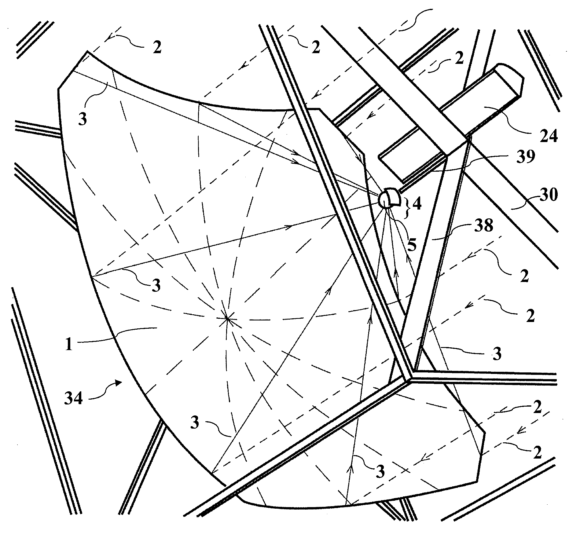
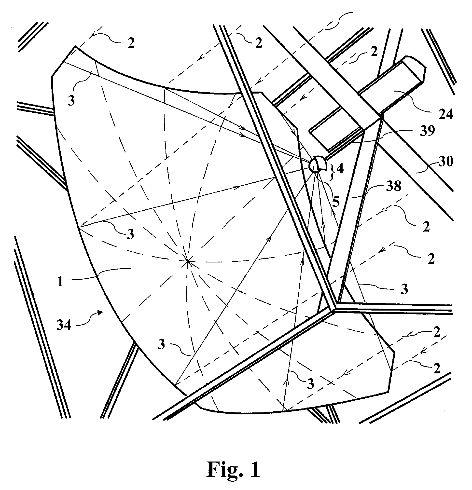
[0115]FIG. 1 is a perspective view of a generator 4 according to the invention, in operation at the focus of a paraboloidal reflector 1. Sunlight enters the system as radiation or rays 2 which are reflected by the mirror 1. The mirror 1 is shaped so that reflected solar radiation or rays 3 are directed toward the focus 28 where a generator 4 is located. In operation, a generator 4 is designed for use at the focus 28 of a preferably paraboloidal reflector or mirror 1 whose axis is pointed at the sun by a two-axis tracker.

[0116]A mirror 1 to supply solar power to a generator according to this invention has preferably a substantially paraboloidal reflecting surface that reflects as much of the sunlight as possible and concentrates it at the location of the generator 4. A paraboloidal shaped reflector 1 is preferred, because it will reflect parallel incoming rays 2 to a focal point 28. In a preferred embodiment wherein the reflector 1 is substantially paraboloidal, deviation of the shap...


PUM

PropertyMeasurementUnit
Angleaaaaaaaaaa
Angleaaaaaaaaaa
Angleaaaaaaaaaa

Abstract

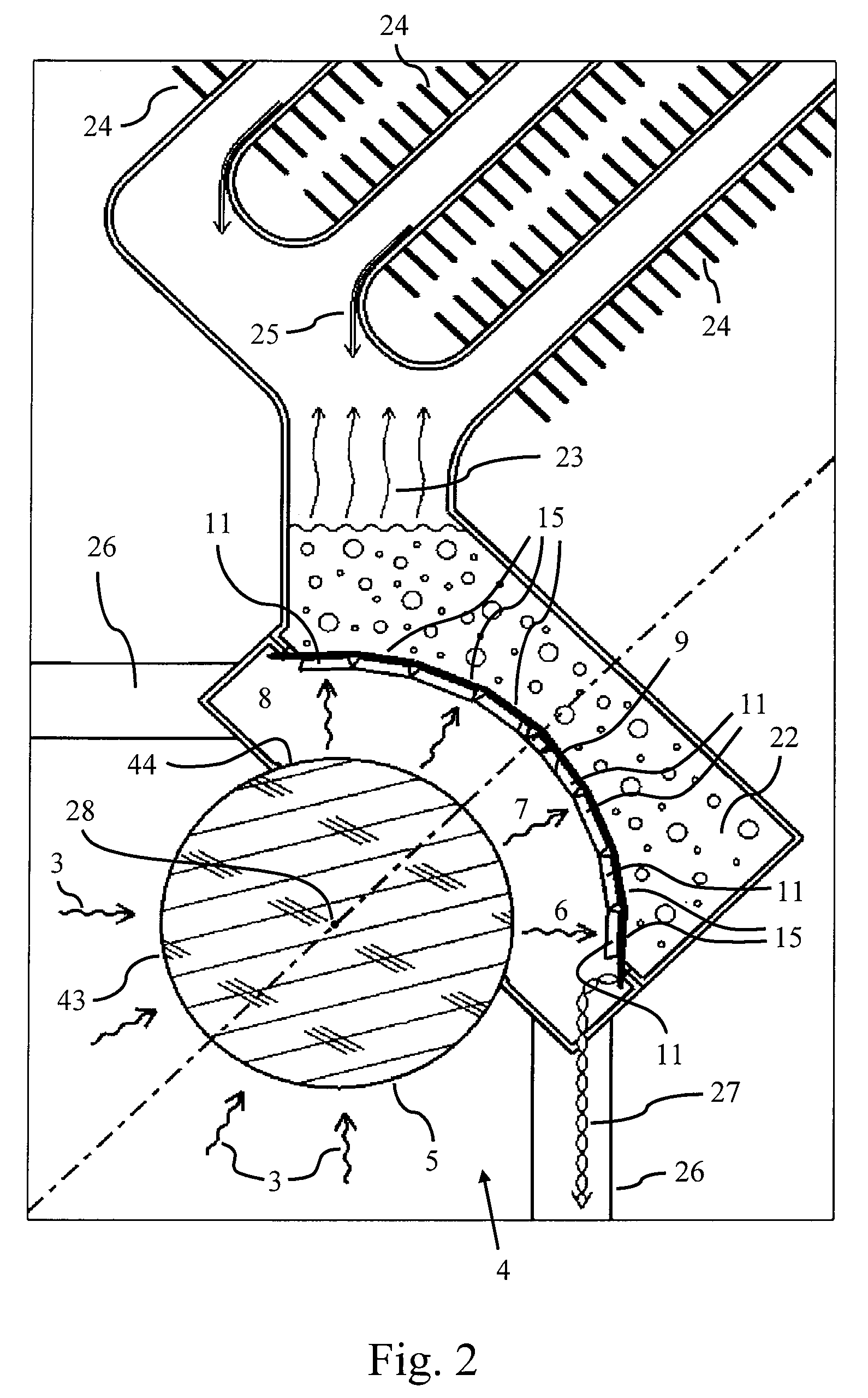
The invention is a generator for photovoltaic conversion of concentrated sunlight into electricity. A generator according to the invention incorporates a plurality of photovoltaic cells and is intended for operation near the focus of a large paraboloidal reflector pointed at the sun. Within the generator, the entering concentrated light is relayed by secondary optics to the cells arranged in a compact, concave array. The light is delivered to the cells at high concentration, consistent with high photovoltaic conversion efficiency and low cell cost per unit power output. Light enters the generator, preferably first through a sealing window, and passes through a field lens, preferably in the form of a full sphere or ball lens centered on the paraboloid focus. This lens forms a concentric, concave and wide-angle image of the primary reflector, where the intensity of the concentrated light is stabilized against changes in the position of concentrated light entering the generator. Receiving the stabilized light are flat photovoltaic cells made in different shapes and sizes and configured in a concave array corresponding to the concave image of a given primary reflector. Photovoltaic cells in a generator are also sized and interconnected so as to provide a single electrical output that remains high and stable, despite aberrations in the light delivered to the generator caused by, for example, mispointing or bending of the primary reflector. In some embodiments, the cells are set back from the image formed by the ball lens, and part of the light is reflected onto each cell small secondary reflectors in the form of mirrors set around its perimeter.

Description

CROSS-REFERENCE TO RELATED APPLICATIONS[0001]This application is based upon and claims the benefit of the filing date of provisional patent application Ser. No. 61 / 127,298, filed May 12, 2008, entitled “Solar Photovoltaic Generator,” the entire disclosure of which is incorporated herein by reference. This application discloses subject matter related to application Ser. No. ______, filed contemporaneously herewith, entitled “Solar Concentrator Apparatus with Large, Multiple, Co-Axial Dish Reflectors,” by Roger P. Angel and Warren B. Davison, the entire disclosure of which is incorporated herein by reference. This application also discloses subject matter related to application Ser. No. ______, filed contemporaneously herewith, entitled “Method of Manufacturing Large Dish Reflectors for a Solar Concentrator Apparatus,” by Roger P. Angel and Blain H. Olbert, the entire disclosure of which is incorporated herein by reference.BACKGROUND OF THE INVENTION[0002]Climate change is recognized ...

Claims


Application Information

Patent Timeline
IPC IPC(8): H01L31/042F24S23/30F24S23/70F24S23/71F24S50/20
CPCC03B23/0256H01L31/0547C03B23/0357F24J2/08F24J2/1057F24J2/12F24J2/38F24J2/523F24J2/5233F24J2/542F24J2002/5458F24J2002/5475F24J2002/5479Y02E10/42Y02E10/47Y02E10/52F24J2002/0084C03B23/0258C03B23/0355H02S40/22F24S2030/145F24S2020/16F24S25/13F24S50/20F24S2030/133F24S25/10F24S30/452F24S2030/14F24S23/82F24S23/30F24S23/71C03B23/0352H01L31/052H01L31/054F24S23/70C03B23/035Y02E10/40
Inventor ANGEL, ROGER P.
Owner THE ARIZONA BOARD OF REGENTS ON BEHALF OF THE UNIV OF ARIZONA
Learn More