Versatile axial fan and centrifugal shutter mechanism

a centrifugal shutter and axial fan technology, which is applied in the field of energy-efficient axial fans, can solve the problems of increasing the overall weight of the shutters, not cleaning, and difficult cleaning of the shutters, so as to reduce the cost of the axial fan, reduce the number of parts and joints, and increase the performance of the fan

Inactive Publication Date: 2004-04-29
MILANA MARISA +1
View PDF15 Cites 15 Cited by
  • Summary
  • Abstract
  • Description
  • Claims
  • Application Information

AI Technical Summary

Benefits of technology

[0043] Another important object of the present invention is to reduce the cost of the axial fan; this objective is possible with a simplification, reduction of the number of parts and joints and increase performance of the fan.
[0044] Another object of the present invention is to provide a shutter assembly mounted either horizontally like the ones of the prior art or preferably vertically for handling very dusty air for preventing dust built up thereto.
[0045] A further object of the invention is to provide a safe centrifugal mechanism, simple in construction, positive in operation, designed to function for long periods of time and in a very large range of speeds without frequent servicing and repairs and adapted to work for pushing or pulling an element to be actuated.
[0046] Another object of the present invention is to provide an affordable, high efficient fan which will require minimal installation space, shipping volume and maintenance.

Problems solved by technology

When said fans operate in dusty atmospheres, if air velocity is lower than the minimum velocity to prevent dust settling, said dust quickly accumulates on them, increasing the overall weight of the shutters.
During the cleaning operation it is possible to damage them, resulting in shutters that will not close or open completely.
Cleaning the shutters is a tough task and therefore, they are not cleaned as often as they should.
Dust built up creates undesirable flow restrictions, which reduce the air flow capacity of the fan and affects the opening and closing of the shutters; as a result it causes undesirable air infiltration and building heat losses.
The air moving capacity of a fan with gravity shutters is also negatively affected by stormy weather.
When the fan with gravity shutters is operating there is a "constant battle" between the air flow, to blow the shutters open and the gravity forces trying to close them, this translates to a continuous oscillation of the shutters, pressure losses, waste of energy, vibrations, wear and reduction of the air flow.
In conventional axial fans, due to the limited capabilities of the prior techniques in manufacturing and producing with precision fan housings and Venturi, the performance of the fans has been limited.
The motorized shutters are relatively too expensive; therefore the art has developed various centrifugal systems for operate said shutters, for fully open and keep them positively open, in spite of the inevitable dust accumulation thereon and in spite of stormy weather.
Moreover, when said fans are in operation said mechanisms push continuously via a thrust bearing the shutter therefore they are subject to continuous friction, oscillations and wear.
If said fans move 30% less air than they should, more fans are necessary to do the work, as a result there are higher electricity bills and increased wear on the fan.
The farm buildings usually require a large number of fans which during hot weather operate continuously 24 hours a day therefore requires a significant energy use.
In dusty environments, the dust or other foreign matter is able to collect to the fan shutters causing the aforementioned problems on the shutters and eventually jamming also the centrifugal shutter mechanism.

Method used


Image

  • Versatile axial fan and centrifugal shutter mechanism
  • Versatile axial fan and centrifugal shutter mechanism
  • Versatile axial fan and centrifugal shutter mechanism

Examples


Embodiment Construction

[0056] The description which follows is to be understood as being teaching disclosure directed to persons of skill in the appropriate art and not limiting upon the present invention of the accompanying drawings which are given by the way of illustration of the most practical embodiments of the present invention. For a better understanding of the invention, reference shall be made to the accompanying drawings.

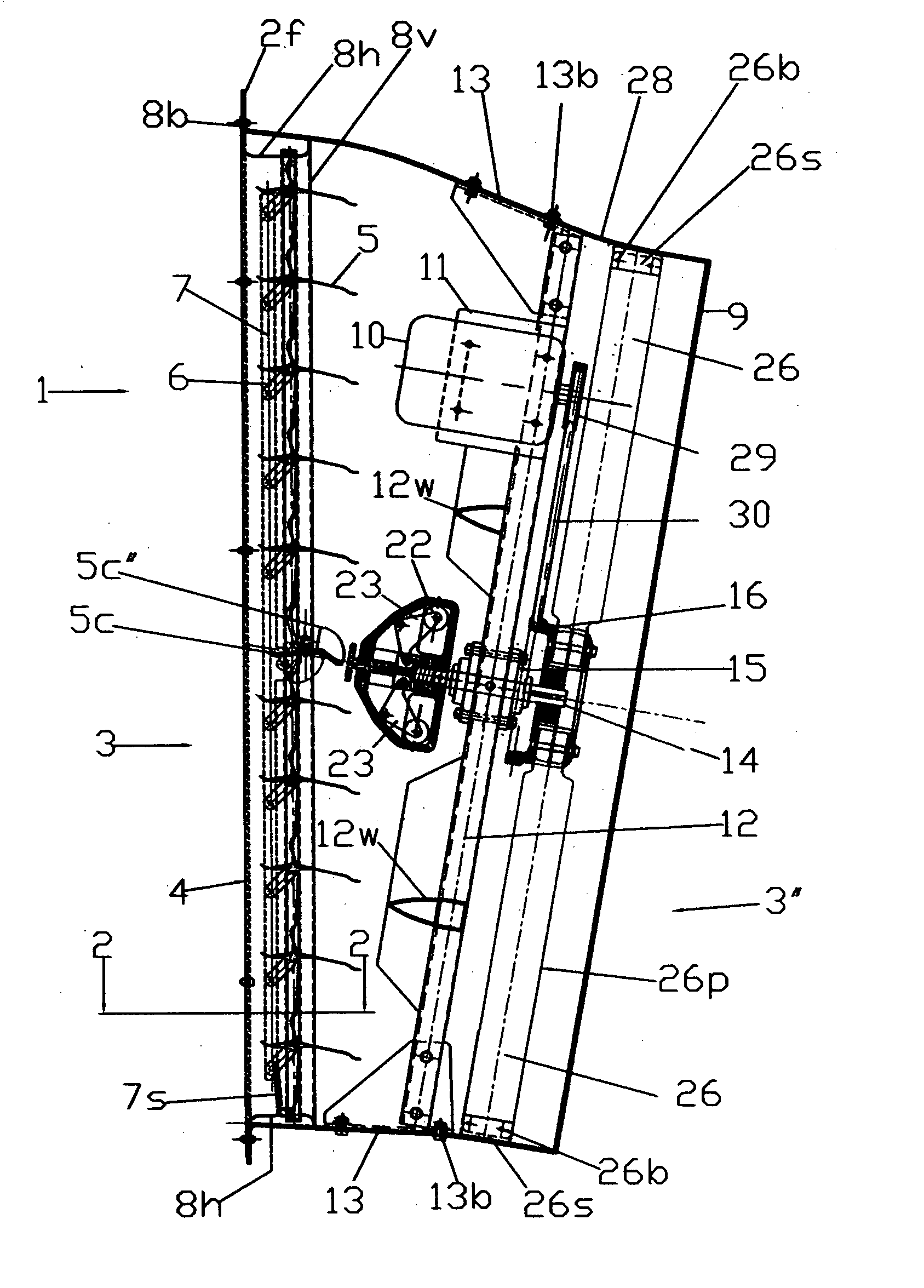
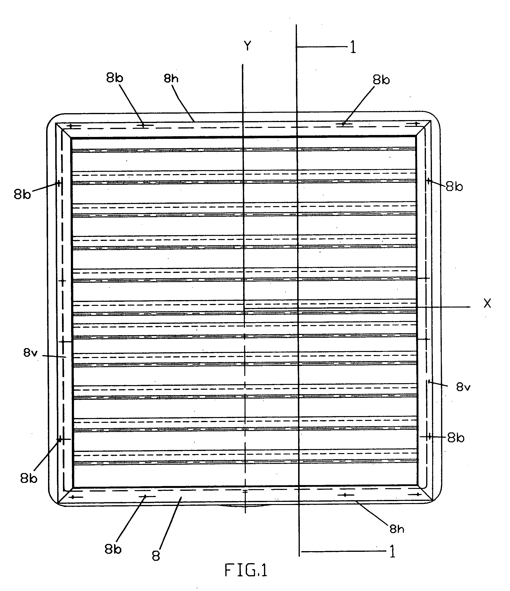
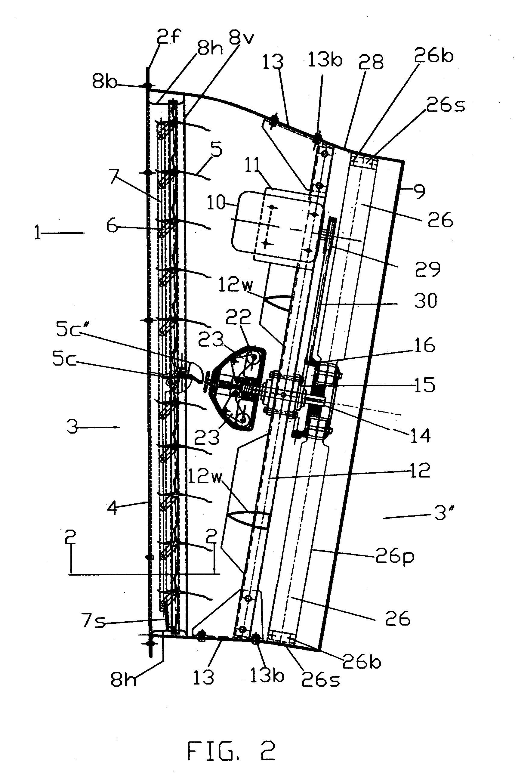
[0057] Referring now to the drawings, on FIGS. 1, 2, the Applicant shows an axial belt driven fan, generally indicated by the reference numeral 1 as a whole. The components of said fan 1 include a compact streamlined housing enclosure 2 having an inner cavity defining an air flow passageway with large radii corners, adapted to be installed into a wall opening of a building at a downwardly slanted angle thereto, so that air flow, drainage and laden dusty air can easily transit therethrough.

[0058] Said compact fan housing is aerodynamically shaped to provide for high airflow and l...


PUM


Abstract

An efficient axial fan has housing with a square inlet opening and a round outlet opening, a fan assembly with a drive motor and a propeller coupled thereto. The entrance of the housing is provided with a shutter assembly disposed horizontally or vertically across the entrance of the fan and comprising a plurality of vanes including a central operative vane operated by a centrifugal shutter mechanism secured to one end of the propeller shaft, opposite to the propeller and adjacent to the operative central vane of the shutter assembly. The centrifugal shutter mechanism is normally provided with a hermetic housing comprising a pair of radial masses operatively connected by means of a pair of pivoting arms to an axial sliding reciprocating actuator which is disposed adjacent to the shutter central operative vane. When the fan is on, the radial masses by centrifugal action rotate the pair of arms which push the axial sliding reciprocating actuator away from the central operative vane allowing an extension spring associated with the shutter assembly to cause the opening of the shutter. When the fan is off, an internal compression spring housed within the axial sliding actuator pushes it against the central operative vane causing the closing of the shutter. The propeller comprises a plurality of radially disposed blades which are entirely surrounded by a Venturi and are provided with means for adjusting the tip blade clearance with the Venturi.

Description

[0001] 1. Field of the Invention[0002] This invention pertains generally to an energy efficient axial fan for exhausting humid, corrosive and dusty air from a variety of buildings, including by way of example: foundries, manufacturing facilities, poultry operations, green houses, etc.[0003] In particular the present invention relates generally to new and useful improvements of an axial fan comprising a shutter operated by a centrifugal mechanism.[0004] 2. Description of the Prior Art[0005] Most axial fans are provided with gravity shutters which, are closed by gravity and opened by the air flow exiting of the fan. When said fans operate in dusty atmospheres, if air velocity is lower than the minimum velocity to prevent dust settling, said dust quickly accumulates on them, increasing the overall weight of the shutters. The heavier the shutters are, the harder it is for the fan to blow air through them, so that the fan moves less air and efficiency is lessened. Therefore, gravity shut...

Claims


Application Information

Patent Timeline
Patent Type & Authority Applications(United States)
IPC IPC(8): F04D25/14
CPCF04D25/14
Inventor MILANA, ANGELO
Owner MILANA MARISA
Why Eureka
Try Eureka