
Hybrid implementation for error correction codes within a non-volatile memory system

Active Publication Date: 2004-04-29
SANDISK TECH LLC
View PDF39 Cites 143 Cited by
  • Summary
  • Abstract
  • Description
  • Claims
  • Application Information

AI Technical Summary

Benefits of technology

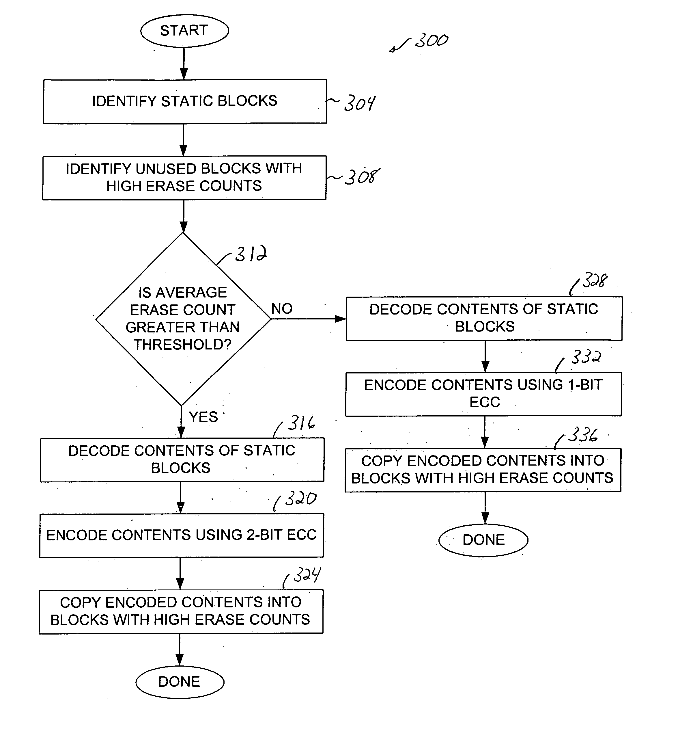
[0014] In one embodiment, the method also includes encoding the data using a second algorithm when it is determined that the data is not to be encoded using the first algorithm, and writing the data encoded using the second algorithm into the first block. In such an embodiment, the first algorithm may be a 1-bit error correction code (ECC) algorithm and the second algorithm may be a 2-bit ECC algorithm.

Problems solved by technology

However, the implementation of a 2-bit ECC algorithm, while providing increased error correction capabilities to stored data, generally involves more calculations and, hence, more computational overhead than the implementation of a 1-bit ECC algorithm.
When more computational overhead is required, more power, e.g., battery power, may be consumed by a non-volatile memory.
As a result, the overall performance of a memory system may be compromised, particularly since the integrity of data that is stored in blocks which have been erased a relatively low number of times is generally relatively high.
1-bit ECC algorithms, however, are often less accurate than 2-bit ECC algorithms.
Further, as blocks into which data is stored near the end of their usable lives, the data stored in such blocks is more likely to contain errors.
As such, when 1-bit ECC algorithms are used to encode data stored in blocks which have been erased a relatively high number of times and to decode such data, the integrity of the data may be compromised, and the performance associated with the blocks may be adversely affected.

Method used


Image

  • Hybrid implementation for error correction codes within a non-volatile memory system
  • Hybrid implementation for error correction codes within a non-volatile memory system
  • Hybrid implementation for error correction codes within a non-volatile memory system

Examples


Embodiment Construction

[0033] An error correction code (ECC) algorithm such as either a 1-bit ECC algorithm or a 2-bit ECC algorithm is often used to encode data to be stored into a physical block of a non-volatile memory, and to decode stored data. The use of ECC algorithms generally enables the accuracy of data stored within a physical block to be improved. The use of a more calculation-intensive 2-bit ECC algorithm may be preferred to a less calculation-intensive 1-bit ECC algorithm due to the ability to of a 2-bit ECC algorithm to correct more erroneous bits that may be corrected using a 1-bit ECC algorithm. The implementation of a 2-bit ECC algorithm, however, while providing increased error correction capabilities, is more expensive than a 1-bit ECC algorithm in terms of a number of calculations and power requirements.

[0034] In many cases, when a block into which data is stored is relatively young and, hence, has not been subjected to a relatively high number of erase cycles, a 1-bit ECC algorithm m...


PUM


Abstract

Methods and apparatus for using different error correction code algorithms to encode and to decode contents of blocks within a non-volatile memory are disclosed. According to one aspect of the present invention, a method for storing data within a non-volatile memory includes identifying a first block into which the data is to be stored, and obtaining an indicator associated with the first block. A determination may then be made regarding whether the indicator indicates that the data is to be encoded using a first algorithm. The data is encoded using the first algorithm when it is determined that the data is to be encoded using the first algorithm, after which point the data encoded using the first algorithm is written into the first block.

Description

[0001] The present invention claims priority of U.S. Provisional Patent Application No. 60 / 421,911, filed Oct. 28, 2002, which is hereby incorporated by reference in its entirety.[0002] The present invention is related to co-pending U.S. patent application Ser. Nos. 10 / 281,739, 10 / 281,823, 10 / 281,670, 10 / 281,824, 10 / 281,631, 10 / 281,855, 10 / 281,762, 10 / 281,696, 10 / 281,626, and 10 / 281,804, as well as co-pending U.S. Provisional Patent Application Nos. 60 / 421,910, 60 / 421,725, 60 / 421,965, 60 / 422,166, and 60 / 421,746, each filed on Oct. 28, 2002, which are each incorporated herein by reference in their entireties.[0003] 1. Field of Invention[0004] The present invention relates generally to mass digital data storage systems. More particularly, the present invention relates to systems and methods for enabling algorithms used to encode data that is to be written into blocks of a non-volatile memory to be dynamically switched.[0005] 2. Description of the Related Art[0006] The use of non-volat...

Claims


Application Information

Patent Timeline
IPC IPC(8): G06F11/10G06F12/16G06F12/00G06F12/02G11C16/02G11C16/04G11C16/06G11C16/08G11C29/00G11C29/04H03M13/00
CPCG06F12/0246G06F11/1068G11C16/02
Inventor CHANG, ROBERT C.QAWAMI, BAHMANSABET-SHARGHI, FARSHID
Owner SANDISK TECH LLC
Learn More