Guide

a technology of guide rods and guides, applied in the field of guides, can solve the problems of high component wear and failure rate, cumbersome adaptation to existing saws, increased costs due to specialized manufacture,

Inactive Publication Date: 2004-05-06
AZIZ EDMUND J +1
View PDF5 Cites 37 Cited by
  • Summary
  • Abstract
  • Description
  • Claims
  • Application Information

AI Technical Summary

Problems solved by technology

These devices are either integral to the saw in use, or are cumbersome in adapting to existing saws through retrofit.
These devices may be readily adapted to existing saws, however they require a large number of components to be placed in a volume limited element affixed to a rapidly spinning saw blade which is subjected to signific

Method used


Image

  • Guide
  • Guide
  • Guide

Examples


Embodiment Construction

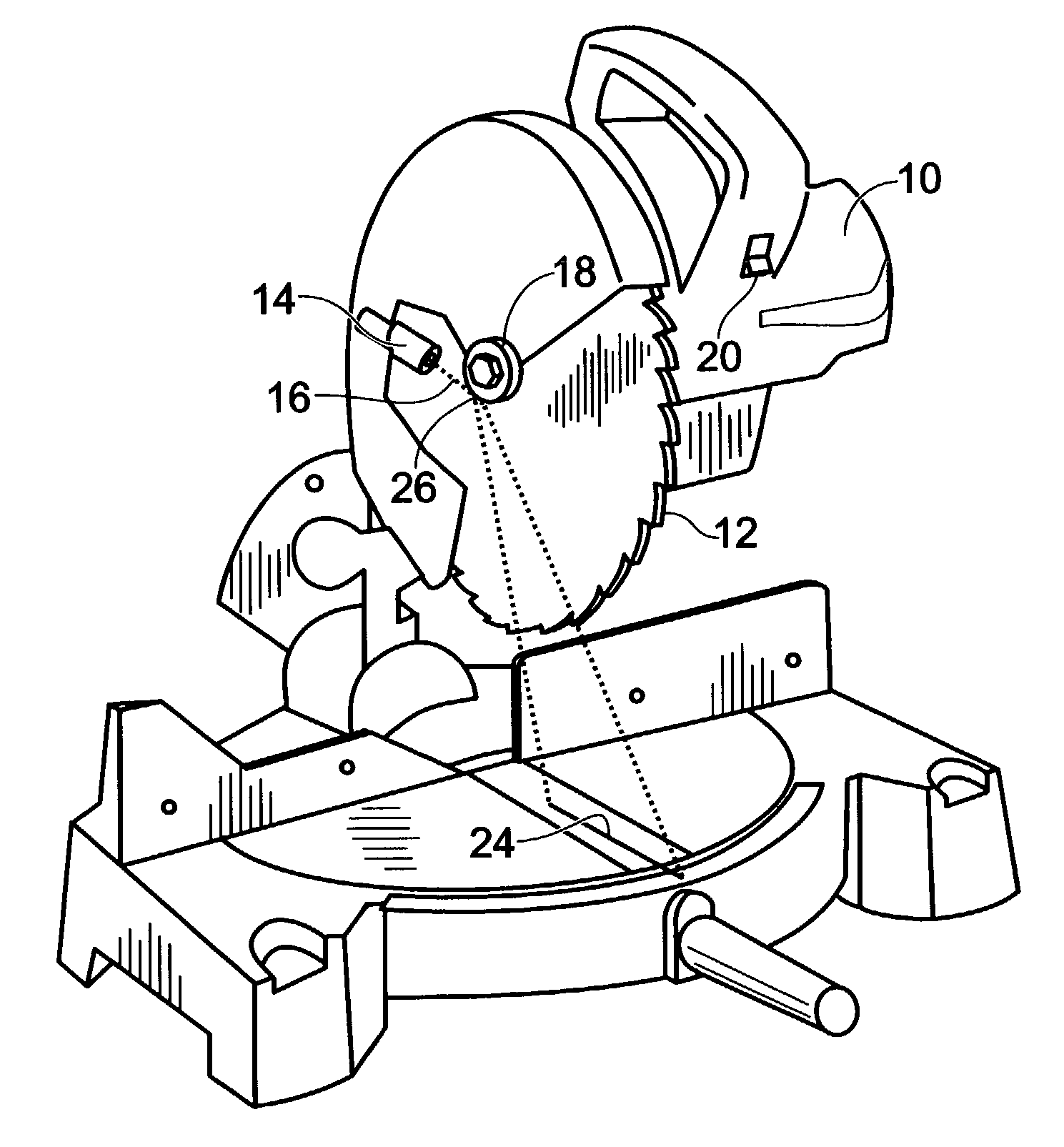
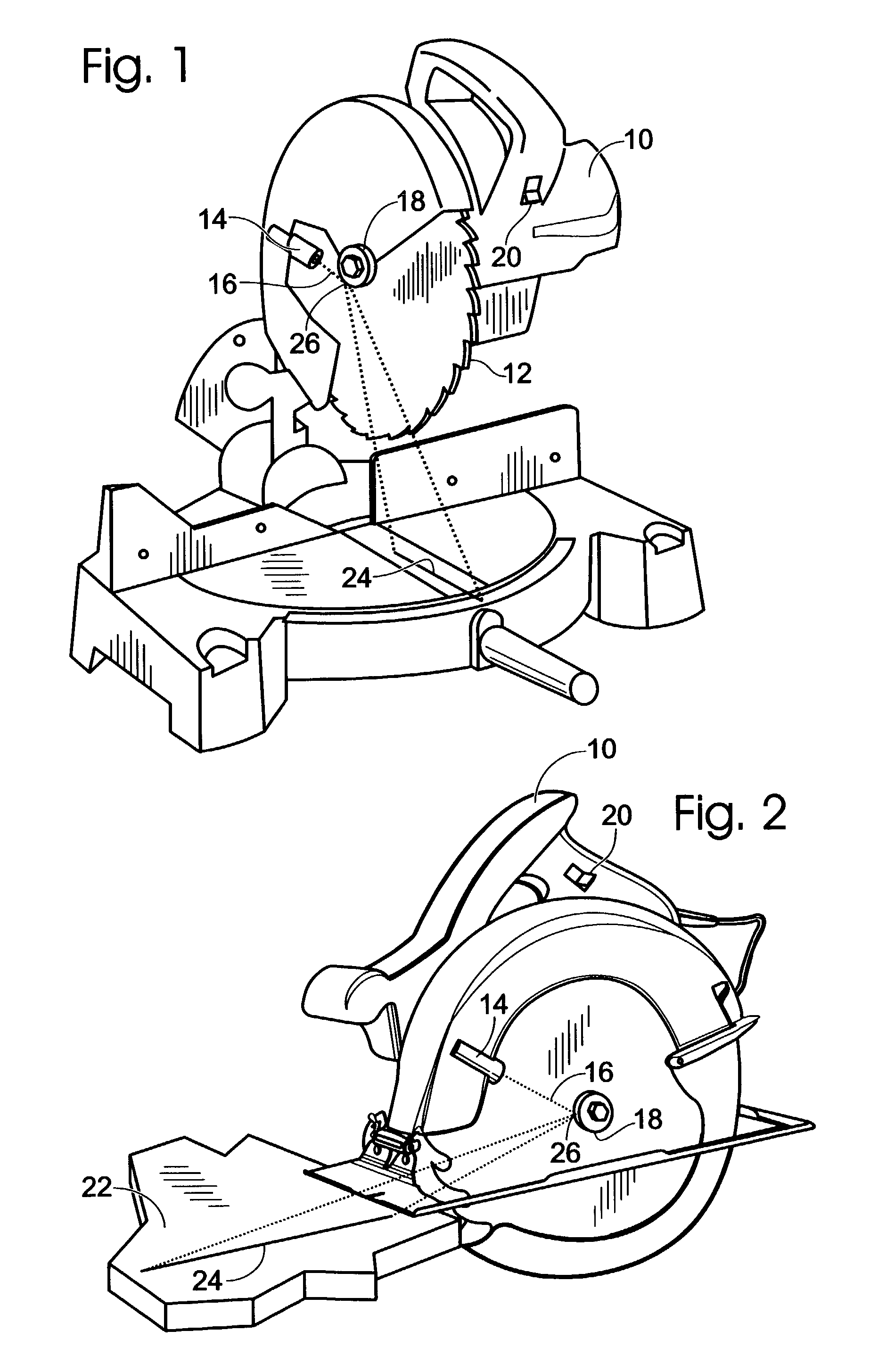
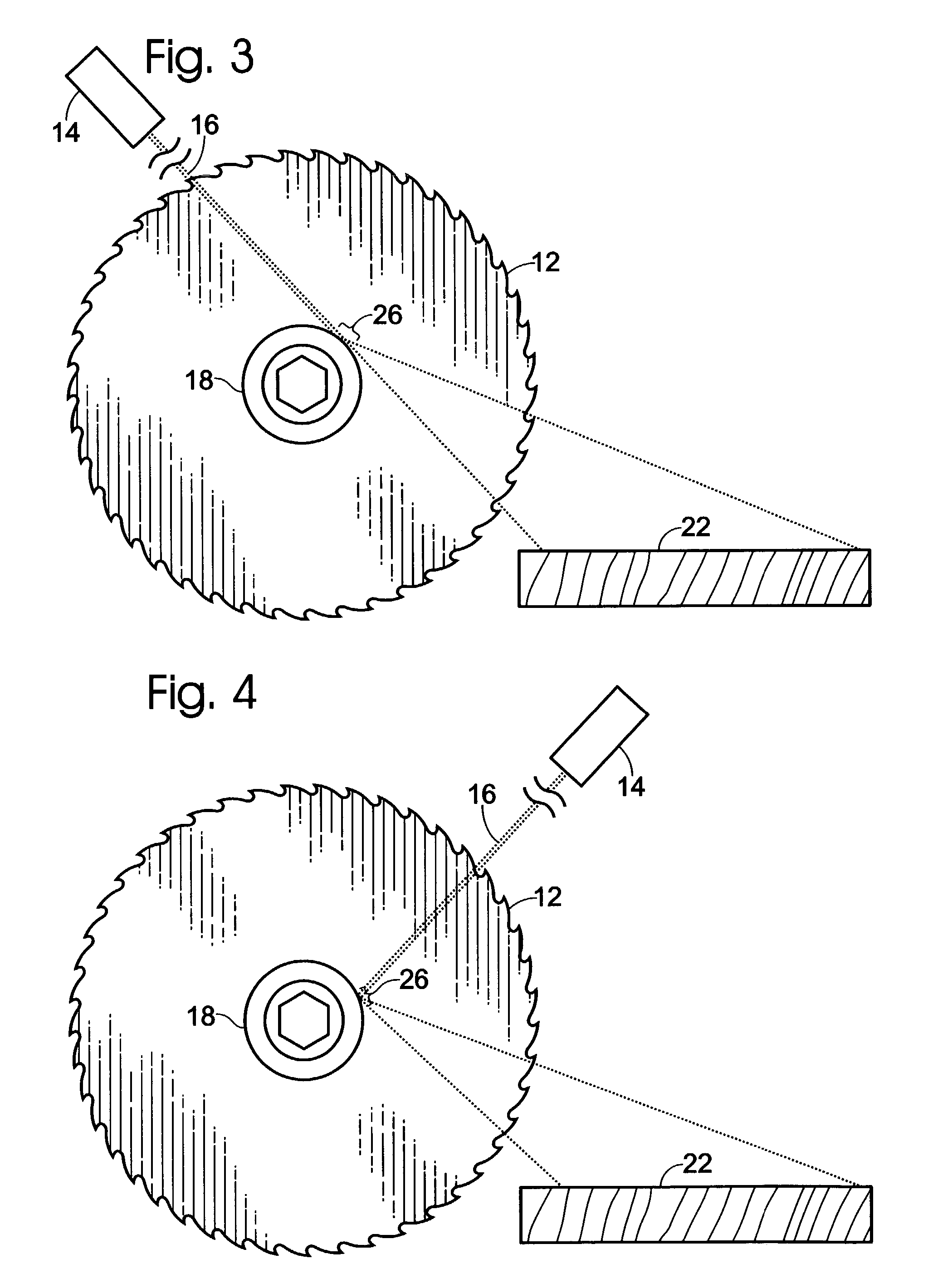
[0025] In the preferred embodiment, a reflector 18 is attached coaxially with a blade 12 for a rotary saw 10. In a conventional saw, a blade bolt is used to hold a blade, washer, arbor and / or lock washer combination and the blade and washer combination are retained by a blade nut. The reflector 18 may be used in place of a lock washer or arbor and held in place in a conventional way. As the reflector 18 occupies the space of existing components on most saws, that of a washer, the invention is readily adapted to existing products. The reflector 18 may be chromed washer, a polished alloy or any suitable material finished with a reflective surface. Though the preferred embodiment utilizes a round mirrored or chromed washer, any reflective surface, faceted or mirrored, proximate and coaxial to the blade 12 may be used.

[0026] A light beam source 14, preferably a laser, is provided for emitting a beam of light 16. The light beam source 14 is located such that there exists a direct line to...


PUM


Abstract

A method and apparatus for providing a guide for use with rotary components such as a rotary saw. In the preferred embodiment the invention is comprised of a rotary saw with a blade, a reflector affixed adjacent and coaxial to said blade, a light beam source, preferably a laser projecting a beam of light co-planer to and at said reflector. The reflector acts as a curved mirror to fan the beam of light creating a guideline coplanar with the rotary component or blade of the rotary saw.

Description

[0001] 1. Field of the Invention[0002] The present invention relates to a guide or method and apparatus for visibly displaying a line for determining the alignment and position of a rotating component. More specifically for displaying a guideline on a work piece along which a cut is to be made in the operation of a rotary saw. In the preferred embodiment, the invention consist of a light beam produced by a laser or like device wherein the light beam is projected onto a reflector coaxially mounted adjacent to a saw blade. The reflector provides a point of divergence for the light beam, creating a guideline indicating the plane of the saw blade.[0003] 2. Prior Art[0004] Rotary saws such as circular saws, chop saws, radial arm saws, miter saws and table saws require that the operator properly align the material being cut with the blade. To this end, there exists light and laser-based cut alignment devices which are mounted in the vicinity of the saw and project a light beam along the c...

Claims


Application Information

Patent Timeline
IPC IPC(8): B23D59/00B23Q17/24
CPCB23Q17/24B23D59/003Y10T83/853Y10T83/828
Inventor AZIZ, EDMUND J.AZIZ, JOHN E.
Owner AZIZ EDMUND J
Why Eureka
Try Eureka