Oil pan structure for four-cycle engine

a four-cycle engine and oil pan technology, which is applied in the direction of lubricant mounting/connection, machines/engines, mechanical equipment, etc., can solve the problems of large outside dimension of the engine, complicated installation of oil strainers in intake pumps, etc., and achieves simple configuration, good workability, and reduce engine height

Inactive Publication Date: 2004-05-06
SUZUKI MOTOR CORP
View PDF5 Cites 29 Cited by
  • Summary
  • Abstract
  • Description
  • Claims
  • Application Information

AI Technical Summary

Benefits of technology

[0017] The invention is accomplished in view of the problems of the convention alart. Accordingly, an object of the invention is to provide an oil pan structure for a four-cycle engine enabled to reduce the height of the engine by constructing a space-saving oil passage with a simple configuration, and as to have good workability.

Problems solved by technology

Thus, the four-cycle engine has a problem in that the outside dimension thereof is large, as compared with that of a two-cycle engine.
However, the conventional art apparatus has problems in that when the capacity of the oil pan is reduced, the routing of an oil strainer to be installed in an intake pump (that is, as cavenging pump) becomes complicated, so that the oil strainer is subjected to shape constraints.
For example, when the oil strainer is formed from a pipe member, the oil strainer is subjected to pipe-diameter and routing constraints because it is impossible to form the oil strainer into a steeply curved shape.
Further, when the oil strainer is formed by resin molding or casting, the apparatus has a problem in that the structure of a stationary part of the oil strainer becomes complicated so as to be prevented from being damaged owing to vibrations thereof.
Therefore, it is difficult to dispose the oil pump at the engine's rear portion in which the placement of an oil gallery is difficult.
With such configuration, when the engine is mounted thereon during a state in which the engine is backwardly tilted, it is difficult to ensure the oil passage led to the scavenging pump.

Method used


Image

  • Oil pan structure for four-cycle engine
  • Oil pan structure for four-cycle engine
  • Oil pan structure for four-cycle engine

Examples


first embodiment

[0030] Hereinafter, the invention is described in detail by referring to the drawings.

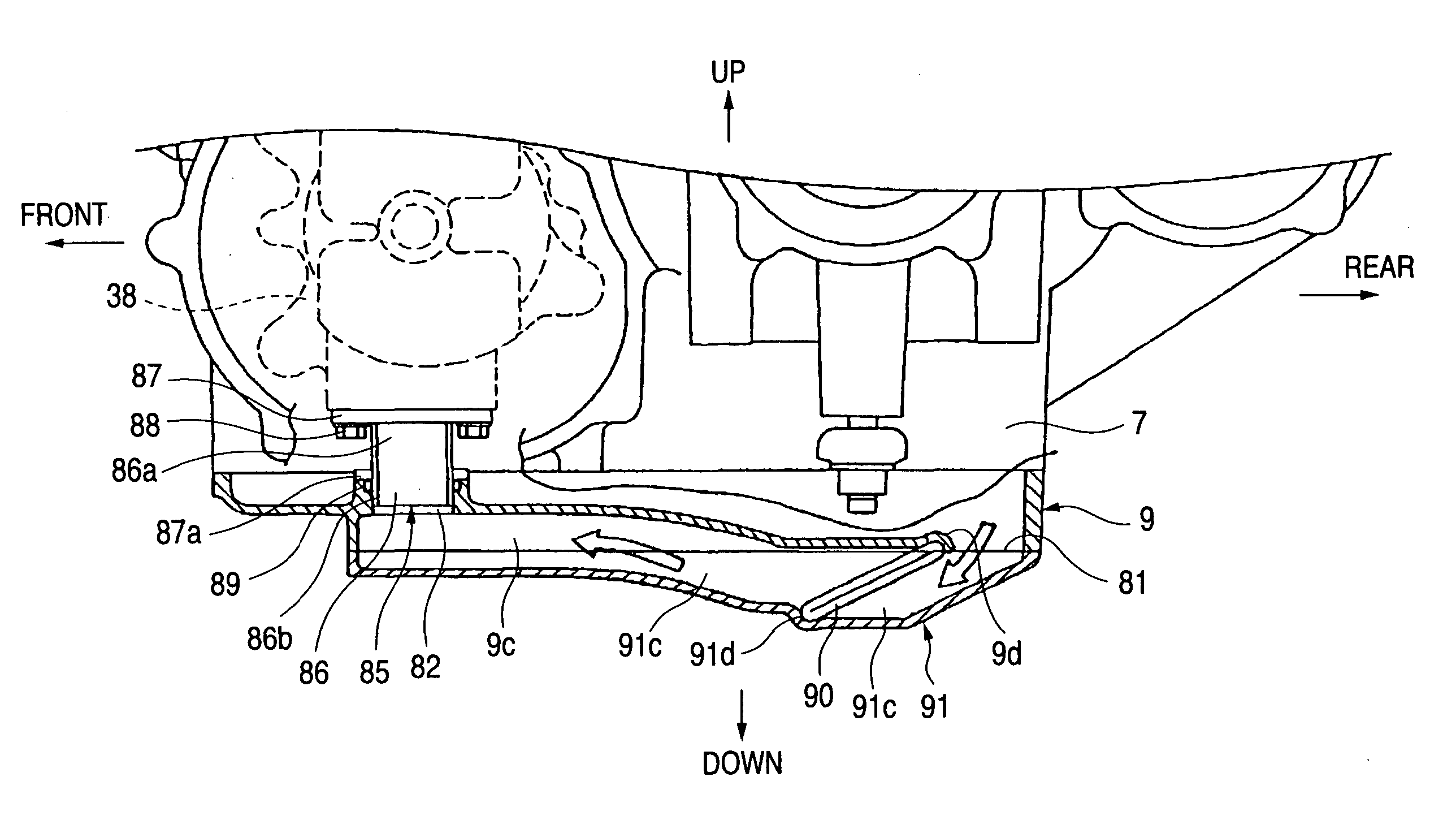
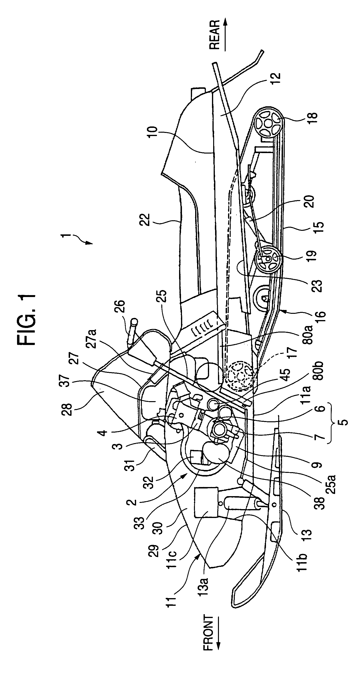
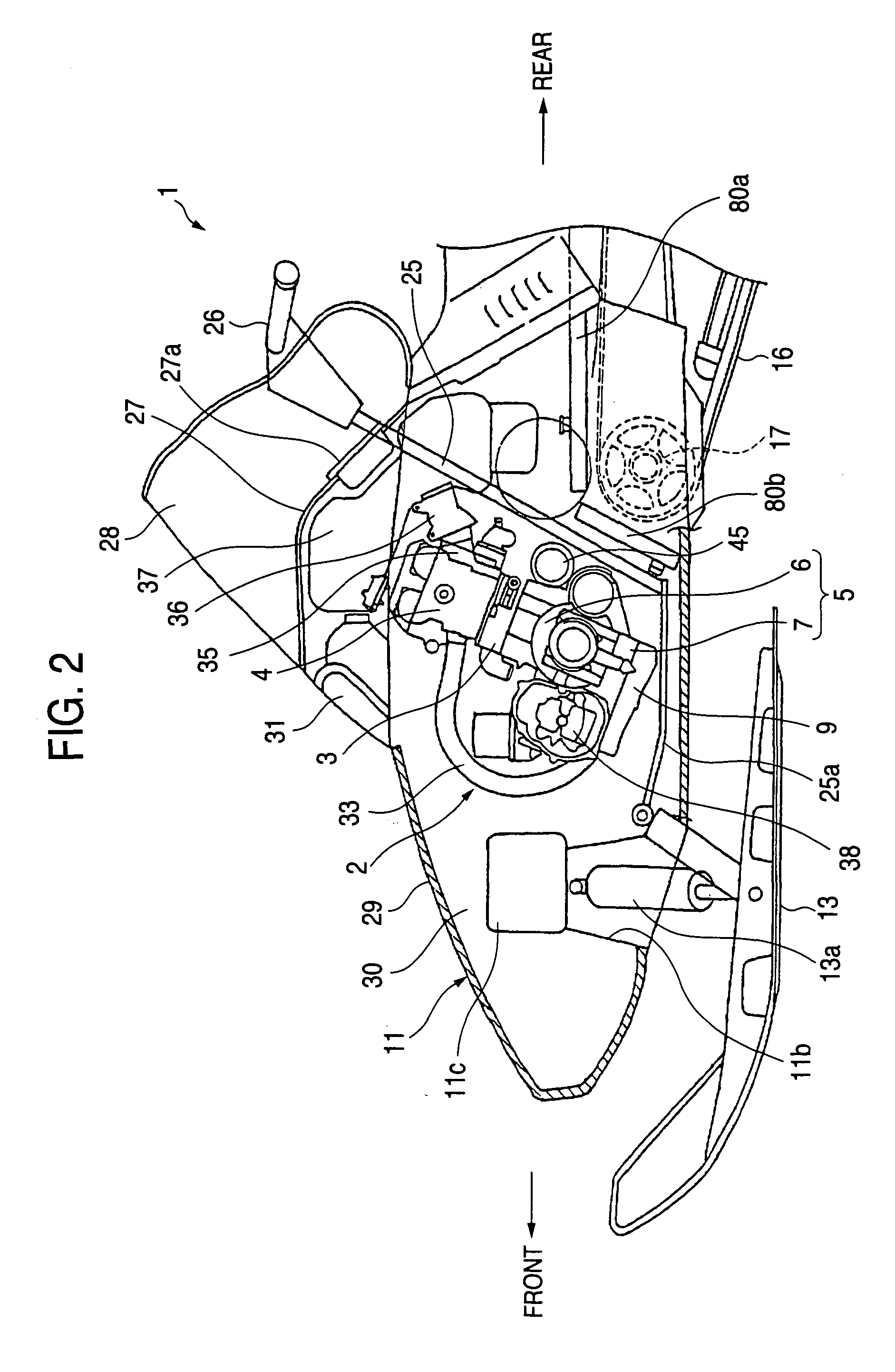
[0031] FIGS. 1 to 5 illustrate the first embodiment of an oil pan structure for a four-cycle engine according to the invention. FIG. 1 is a side view illustrating the entire configuration of a snowmobile employing an oil pan structure for a four-cycle engine according to the embodiment of the invention. FIG. 2 is a side sectional view illustrating the configuration of a front portion of the vehicle body of the snowmobile. FIG. 3 is a side view illustrating the configuration of an engine according to this embodiment, taken from the left side thereof. FIG. 4 is a partially sectional view illustrating the configuration of an oil pan of the engine. FIG. 5 is a view taken along an arrow A in FIG. 3. FIG. 6 is a plan view illustrating the oil pan taken from below.

[0032] In the figures, the same reference character designates the same constituent element.

[0033] This embodiment is obtained by constructing ...

second embodiment

[0084] Next, the invention is described with reference to the accompanying drawings.

[0085] FIG. 7 is a side view illustrating the configuration of an oil pan structure for a four-cycle engine according to the second embodiment of the invention. FIG. 8 is a plan view illustrating the configuration of the oil pan, which is taken from below.

[0086] Incidentally, in these figures, an element designated by the same reference character, which denotes a constituent element of the first embodiment in the figures illustrating the first embodiment, designates the same constituent element. Thus, the description of such a constituent element is omitted.

[0087] As illustrated in FIGS. 7 and 8, the second embodiment is an oil pan structure for a four-cycle engine, which has a configuration that is nearly similar to the configuration of the oil pan structure according to the first embodiment. In the second embodiment, the bottom portion 109a of an oil pan 109 is formed by being swelled nearly like a...


PUM


Abstract

An oil pan structure for a four-cycle engine, in which oil stored in an oil pan is sucked up by an oil pump through an oil strainer and in which oil lubrication is performed by supplying the sucked oil again to each of parts of the engine to be lubricated. In this oil pan structure, a bottom portion of the oil pan is formed nearly like a bowl by being swelled to a side, which is opposite to a crankcase, from an attaching peripheral portion, to which a crankcase lower-part is attached, toward a central portion thereof. An oil pan cover covering a part of the bottom portion is separately provided thereon. Oil passages and are formed from the oil pan cover and the bottom portion. An oil introduction opening portion and an oil suction opening portion 82 are formed in the bottom portion.

Description

[0001] The present invention generally relates to a four-cycle engine and, more particularly, to an oil pan structure effective in a four-cycle engine, in which oil lubrication is performed by a forced oil feed method.[0002] In recent years, demands for exhaust emission control and improvement of fuel economy against environment problems have promoted the employment of four-cycle engines to be mounted on vehicles.[0003] However, the four-cycle engine requires an oil pan to be provided in a lower part thereof so as to perform oil lubrication of each part of the engine. Thus, the four-cycle engine has a problem in that the outside dimension thereof is large, as compared with that of a two-cycle engine.[0004] Therefore, it is desired that a four-cycle engine to be mounted on a vehicle, such as a small snowmobile, which has limited storage space, is small and saves space as much as possible.[0005] Hereinafter, oil lubrication to be performed in a conventional four-cycle engine is descri...

Claims


Application Information

Patent Timeline
Patent Type & Authority Applications(United States)
IPC IPC(8): F01M11/00F01M5/00F01M11/03F01P11/08F02F7/00
CPCF01M11/0004F01M2011/007F01M2011/0066
Inventor MORII, HIDESHISEKIMOTO, OSAMU
Owner SUZUKI MOTOR CORP
Why Eureka
Try Eureka