
Measuring circuit arrangement for electricity meters for direct connection

a technology of electricity meters and circuits, applied in voltage/current isolation, power measurement by current/voltage, instruments, etc., can solve the problems of direct current tolerant current transformers that cannot cope with the maximum permissible phase shift, direct current tolerant current transformers that are more expensive than conventional current transformers, and correction is in itself frequency dependen

Inactive Publication Date: 2004-05-13
LANDIS & GYR AG
View PDF6 Cites 5 Cited by
  • Summary
  • Abstract
  • Description
  • Claims
  • Application Information

AI Technical Summary

Benefits of technology

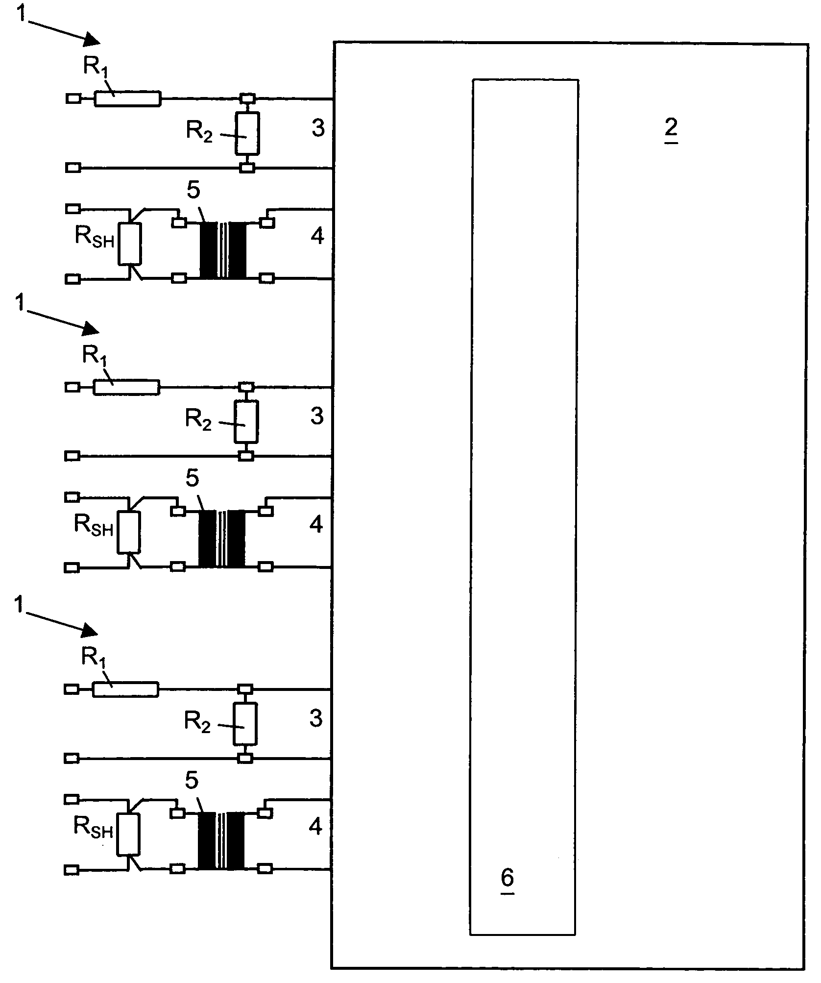
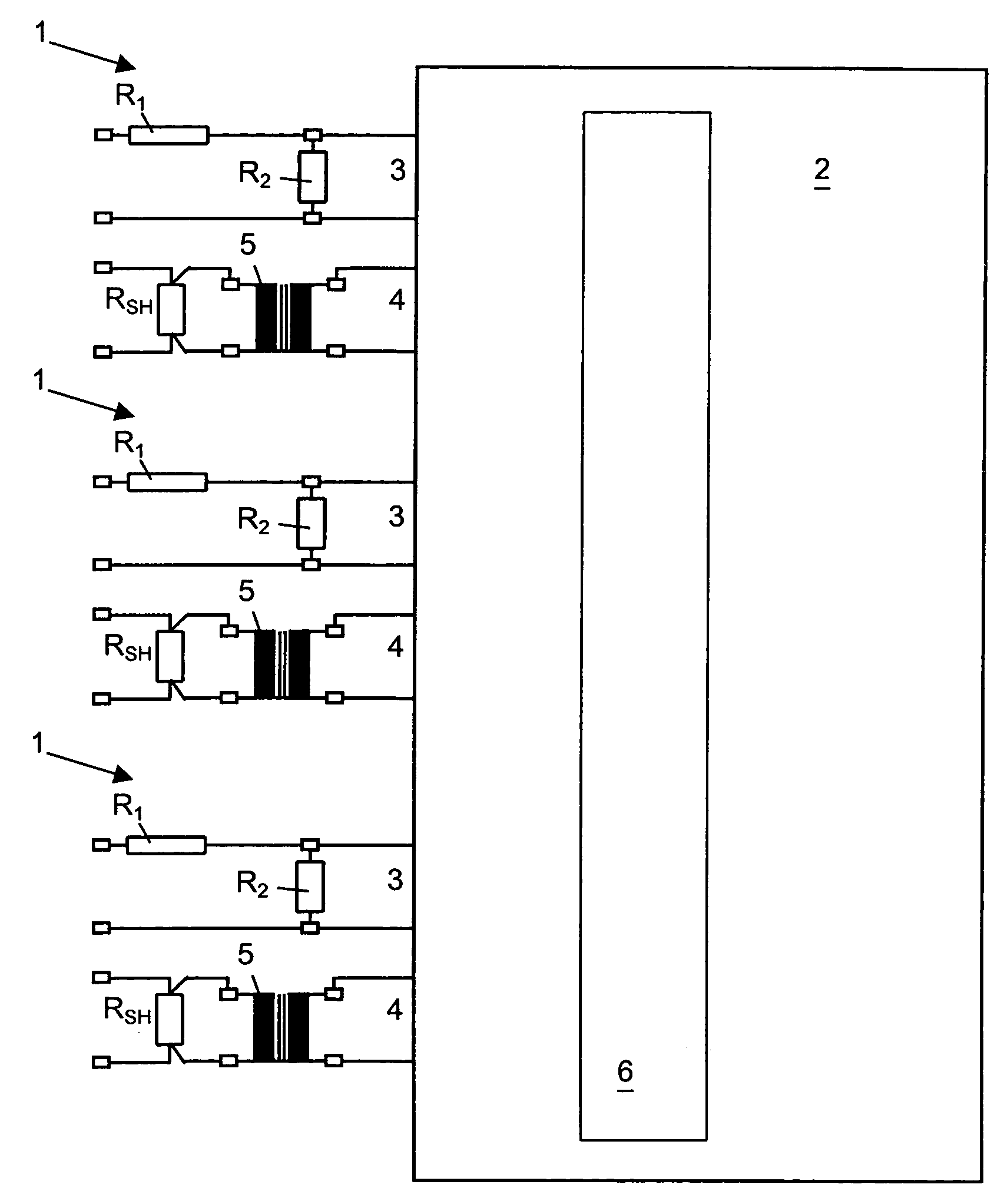
[0009] The essential of the invention consists in the fact that for electricity meters for direct connection, a measuring shunt connected in series upstream of a voltage transformer transforms the current to be measured into a voltage, the voltage transformer being both ready to galvanically isolate the downstream measuring chip, and also capable of tolerating a direct current load with the limits laid down by the standards without exceeding standard limits for angle error between current and voltage. It must be emphasized that the voltage transformer is matched in such a way that its ohmic resistance is simultaneously large enough not to be saturated by a maximum direct current proportion within standard limits of the current to be measured and nevertheless small enough so that maximum standard angle error in combination with the inductance of the transformer is not exceeded.

Problems solved by technology

Measuring circuit arrangements that use direct current tolerant current transformers with direct current tolerance up to .ltoreq.I.sub.max / .pi. are known, but these direct current tolerant current transformers are unable to cope with the maximum permissible phase shifts, as phase shifts of up to 5.degree. between current and voltage measurement values can arise in them.
This means that direct current tolerant current transformers, which are more expensive than conventional current transformers because of the special materials that have to be selected, have to be complemented with a suitable phase compensation arrangement involving yet further expense.
For this reason, the correction of phase shift installed in conventional meters is only possible within narrow limits by time delay, in addition to which, this correction by means of time delay is not coupled to frequency, so that such correction is in itself frequency-dependent, and therefore limited.
In this respect, the fact has also been taken into account until now that for a given current density, and due to their design, current transformers are larger, heavier and hence more expensive in comparison to other sensors, such as voltage transformers, for example.

Method used


Image

  • Measuring circuit arrangement for electricity meters for direct connection
  • Measuring circuit arrangement for electricity meters for direct connection
  • Measuring circuit arrangement for electricity meters for direct connection

Examples


Embodiment Construction

[0012] The sole figure shows a measuring circuit arrangement 1 for electricity meters for direct connection which, for each phase of a three-phase supply, has an input 3 for the voltage measurement and an input 4 for the current measurement of a measuring chip 2. This measuring chip 2 is provided with a correction device 6 for the purpose of phase compensation between voltage values and current values. Upstream from the input 3 for voltage measurement is a voltage divider comprising a first resistance R.sub.1 and a second resistance R.sub.2, which lowers the voltage for measurement to a voltage level suitable for the measuring chip 2 connected in series downstream from it.

[0013] Immediately before the input 4 for the current measurement a voltage transformer 5 is installed which also has a measuring shunt RSH installed in series upstream from it. The current to be measured that flows through the measuring shunt RSH induces in this measuring shunt RSH a drop in voltage proportional t...


PUM


Abstract

A measuring circuit arrangement (1) for an electricity meter for direct connection is respectively connected, for each phase of a three-phase network, to an input (3) for voltage detection and to an input (4) of a measuring chip (2) for detection of the electric current. A voltage divider (R1,R2) used for voltage level adaptation is provided upstream from the input (3) for voltage detection. A current transformer (5) with a series connected measuring shunt (R?SH#191) is installed upstream from the input (4) for current detection. The current transformer (5) is embodied in such a way that the ohmic resistance to the measuring shunt (R?SH#191) sufficiently limits standard direct-current impingement of the current transformer (5) and said ohmic resistance is small enough so that, together with the inductance of the current transformer (5), it only exhibits a standard angle error.

Description

[0001] The invention concerns the field of metering technology. It concerns a measuring circuit arrangement for voltage measurement and current measurement for electricity meters for direct connection.PRIOR ART[0002] In industrial applications, electronic electricity meters have already largely replaced electromechanical meters due to the advantages that they offer. Connection of these industrial meters as at present known is indirect, that is to say through current transformers or voltage transformers displaying the corresponding standard characteristics. Among the outstanding characteristics of electronic meters, particular mention should be made of the fact that they can be read at a distance, require no maintenance, are compact, highly accurate and capable of handling a wide range of current.[0003] As a consequence of these clear advantages over electromechanical meters, the use of electronic electricity meters is also of growing importance for household metering. A fundamental ...

Claims


Application Information

Patent Timeline
Patent Type & Authority Applications(United States)
IPC IPC(8): G01R11/42G01R15/14G01R21/06
CPCG01R11/42G01R21/06G01R15/146G01R15/142
Inventor DE VRIES, JACOBULRICH, ADRIAN
Owner LANDIS & GYR AG
Learn More