
Producing method of optical film

a production method and film technology, applied in the direction of instruments, polarizing elements, applications, etc., can solve the problems of reducing productivity, increasing the amount of unusable parts of polarizing sheets, and both end portions of continuous polarizing sheets cannot be used

Inactive Publication Date: 2004-05-27
FUJIFILM HLDG CORP
View PDF7 Cites 28 Cited by
  • Summary
  • Abstract
  • Description
  • Claims
  • Application Information

AI Technical Summary

Benefits of technology

[0011] According to the present invention, when the length of the remaining first polymer film becomes small, a trailing end of the first polymer film and a leading end of the second polymer film are overlaid. Then these overlaid ends of the first and second polymer films is thermally melt-adhered. A line width of the thermal melt-adhered part is 1-10 mm. Accordingly, after the first and second polymer films are connected, they are not broken or cut in the processes of the liquid treating, the expanding and the drying in the film expanding system. Further, the length from the thermal melt-adhesion line to the front or rear end point of the first and second polymer films is at most 10 mm, preferably 0 mm. Thus the waste of the polymer film is reduced and the treatment nonuniformity is prevented.

Problems solved by technology

In this case, however, the both end portions of the continuous polarizing sheet cannot be used.
Especially, when it is designate to obtain the large size of the blanked polarizing sheet, then the amount of the unusable part of the polarizing sheet becomes larger, and the productivity becomes lower.
As the results, the amount of the waste increases.
However, the tentering device is not only used for expanding the film just after the production thereof.

Method used


Image

  • Producing method of optical film
  • Producing method of optical film
  • Producing method of optical film

Examples


Embodiment Construction

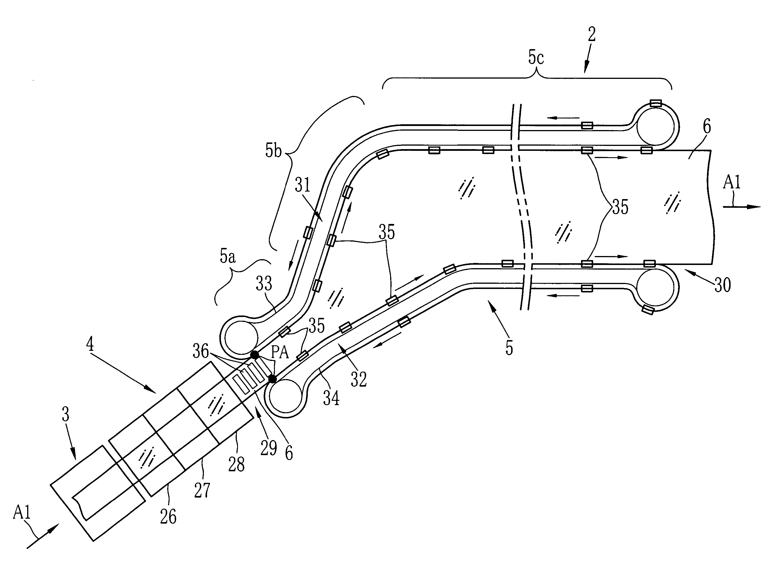
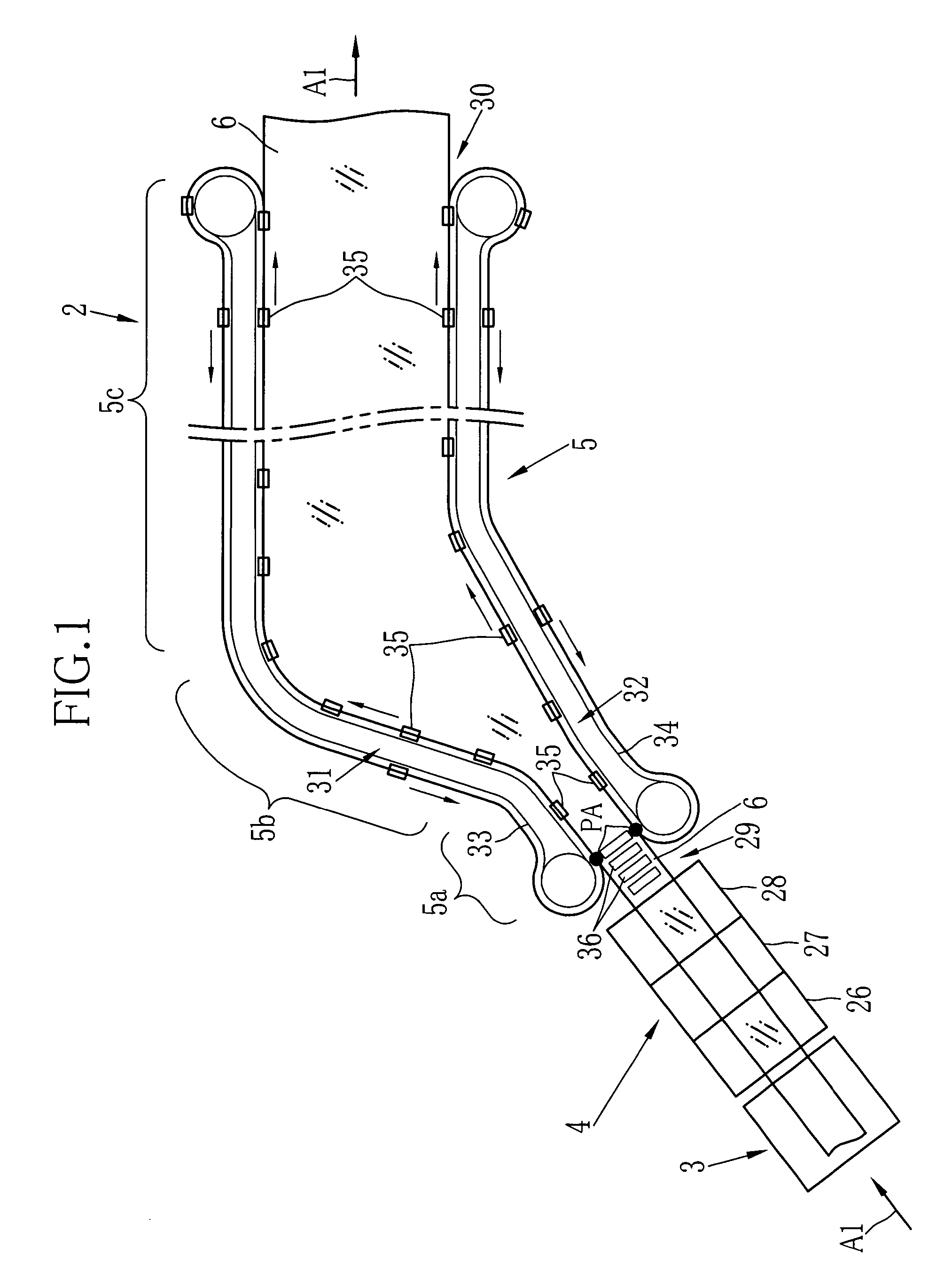
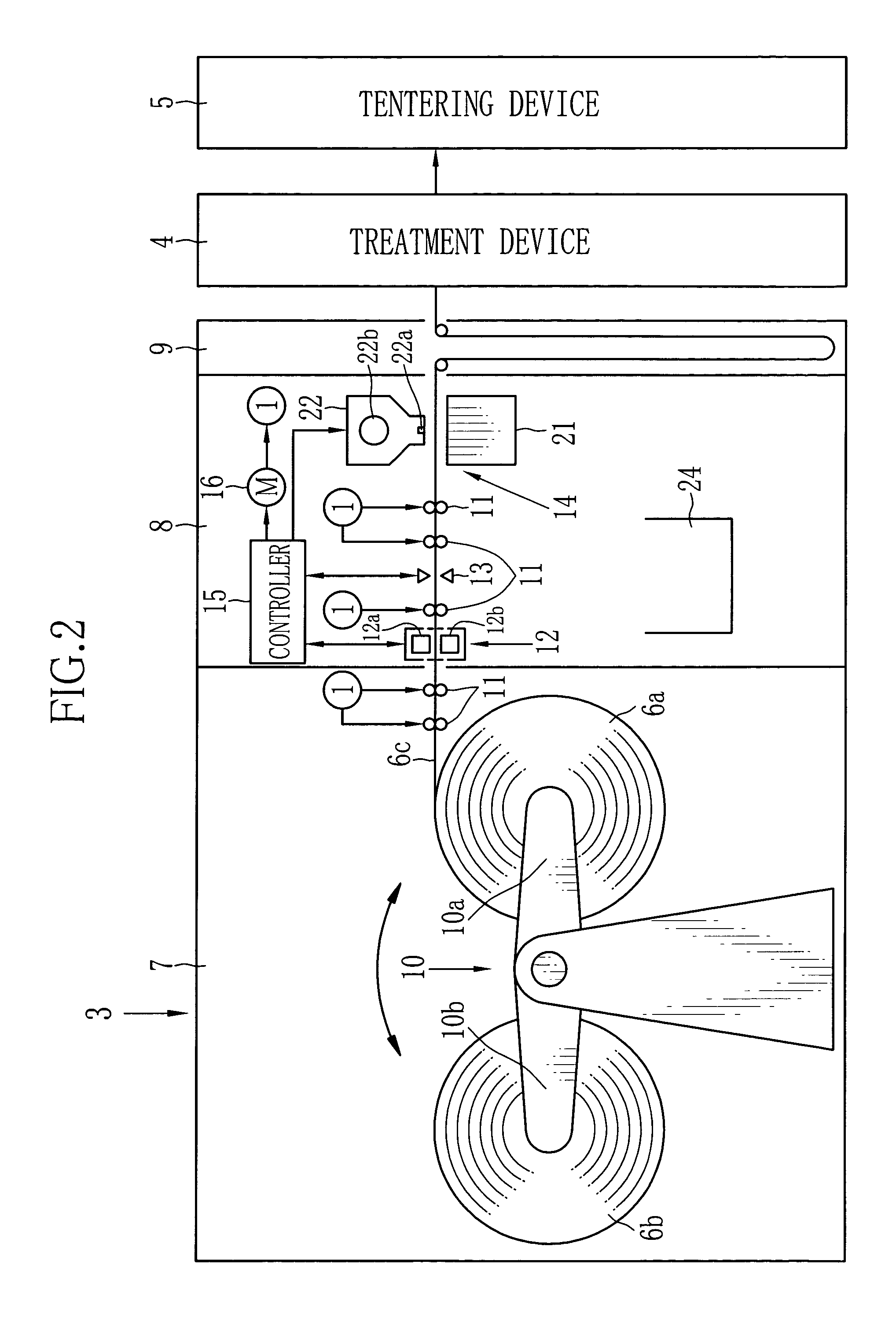
[0022] In FIG. 1, a PVA film expanding system 2 for expanding a PVA film (or polyvinylalcohol film) 6 is constructed of a film supply device 3, a treatment device 4 and a tenter or tentering device 5. As shown in FIG. 2, the film supply device 3 is constructed of a film containing section 7, a film connecting section 8 and a reservoir 9. In the film containing section 7 are contained first and second film rolls 6a, 6b, in which a first PVA film 6c and a second PVA film 6d (see, FIG. 4) are wound respectively. Note that the PVA film 6 (FIG. 1) is used as a general term of the first and second PVA films 6C, 6d.

[0023] The film containing section 7 has a turret arm 10 for rotatably holding the first and second film rolls 6a, 6b. The turret arm 10 is provided with two attachment shafts 10a and 10b. While the first PVA film 6c in a film supply position is unwound and transported from the first film roll 6a attached to the attachment shaft 10a, then the second film roll 6b is set to the at...


PUM

PropertyMeasurementUnit
Widthaaaaaaaaaa
Distanceaaaaaaaaaa
Distanceaaaaaaaaaa

Abstract

When it is complete to unwind a first PVA film from a first film roll, it is started to unwind a second PVA film from a second film roll. A trailing end portion of the first and second PVA film and a leading end portion of the second PVA film are overlaid at a film connecting position. A receive stage and a seal head of a heat sealer sandwiches overlaid portions, and a head body of the seal head heats them so as to thermally melt and adhere the first and second PVA films. During the thermal melt-adhesion, a thermal melt-adhesion line is formed in the overlaid portions of the first and second PVA films.

Description

[0001] 1. Field of the Invention[0002] The present invention relates to a producing method of an optical film.[0003] 2. Description Related to the Prior Art[0004] The spread of a liquid crystal display (hereinafter LCD) rapidly increase the demand of a polarizing sheet. The polarizing sheet is constructed of a polarized film which usually has a polarization character, and a protective film which is adhered with an adhesive agent to one or each surface of the polarized film. As a main material of the polarized film, polyvinylalcohol (hereinafter PVA) is usually used. A PVA film formed of the PVA is expanded or stretched in one axial direction and thereafter dyed with a dichromatic dye or boron. Otherwise the PVA film is dyed and thereafter expanded. Further, the cross-linking on the PVA film is carried out with boron compounds to form the polarized film. Usually, the PVA film is expanded in a lengthwise direction as the one axial direction. Accordingly, the absorbing axis of the pola...

Claims


Application Information

Patent Timeline
IPC IPC(8): B29C55/02B29C55/04B29C55/16B29C65/02B29K29/00B29L11/00G02B5/30
CPCB29C55/045B29C55/165B29C66/71B29K2029/04G02B5/3033B29C65/00B29C65/18B29C65/305B29C66/1122B29C66/43B29C66/73921B29C66/83221B29C66/853B29C66/91421B29C66/919B29C66/929B29C66/942B29C66/949B29C66/9674
Inventor NODA, YOSHIAKISHIINO, TATSUOFUKUZAWA, KIYOSHIMORI, RYO
Owner FUJIFILM HLDG CORP
Learn More