Device for generating a mixture of reducing agent and air

a technology of reducing agent and air, which is applied in the direction of machine/engine, water supply installation, separation process, etc., can solve the problems of large structural size, large structural size, and complex design of devices

Inactive Publication Date: 2004-05-27
ROBERT BOSCH GMBH
View PDF5 Cites 27 Cited by
  • Summary
  • Abstract
  • Description
  • Claims
  • Application Information

AI Technical Summary

Problems solved by technology

Such devices often have a complicated design, with many components, and with a large structural size.
Once again thi

Method used


Image

  • Device for generating a mixture of reducing agent and air
  • Device for generating a mixture of reducing agent and air
  • Device for generating a mixture of reducing agent and air

Examples


Embodiment Construction

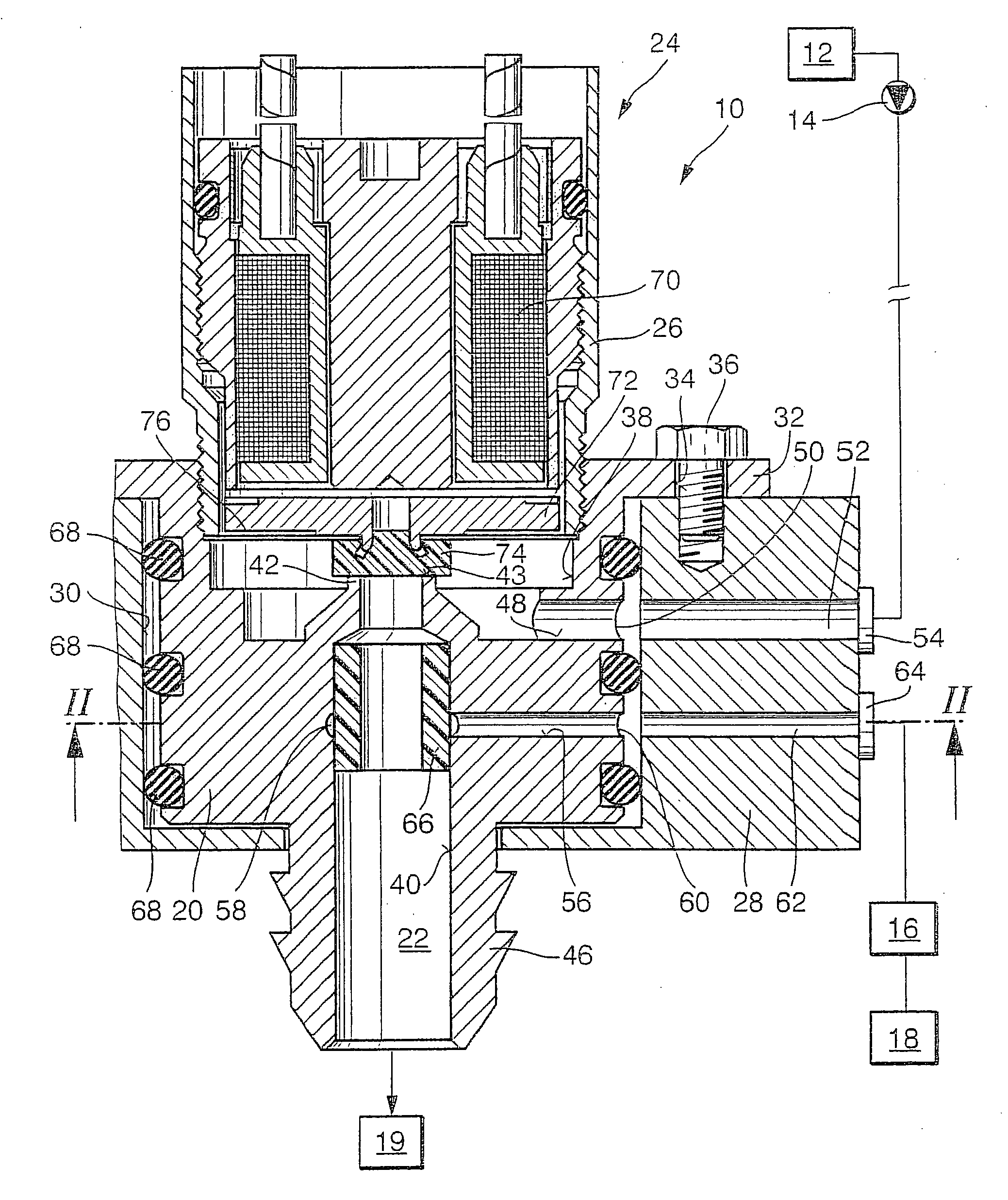
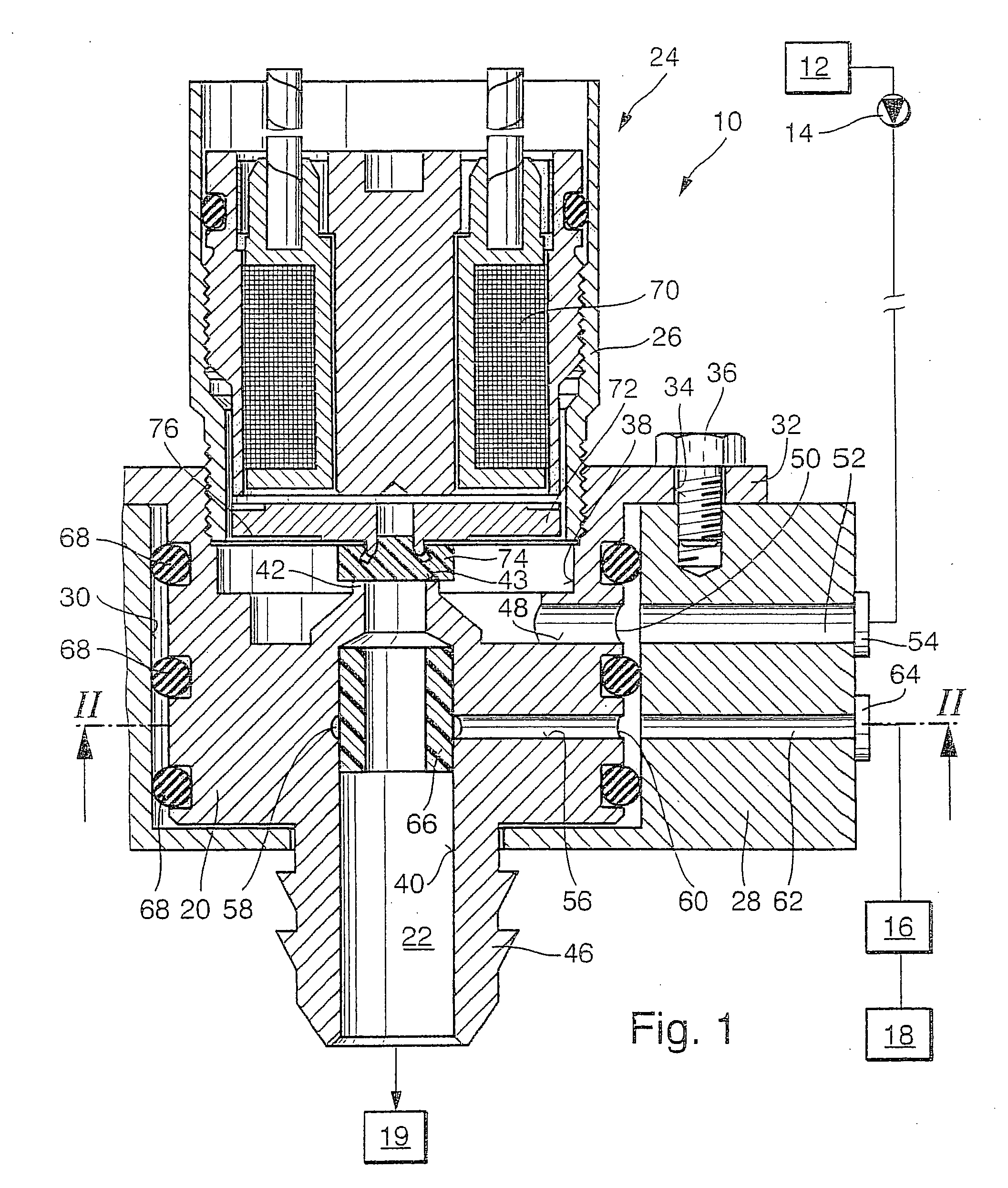
[0006] In FIGS. 1 and 2, a device 10 for generating a mixture of reducing agent and air is shown, which is a component of a system for posttreating exhaust gas of a self-igniting internal combustion engine. The system has a container 12 for reducing agent, which can for instance be an aqueous urea solution. The liquid reducing agent is pumped to the device by means of a pump 14. The system furthermore has a compressed-air reservoir 16, into which, by means of a compressor 18, air is pumped and pressure is generated. From the compressed-air reservoir 16, compressed air is delivered to the device 10 via a line. The mixture of reducing agent and air generated by the device 10 is delivered to a reduction catalytic converter 19.

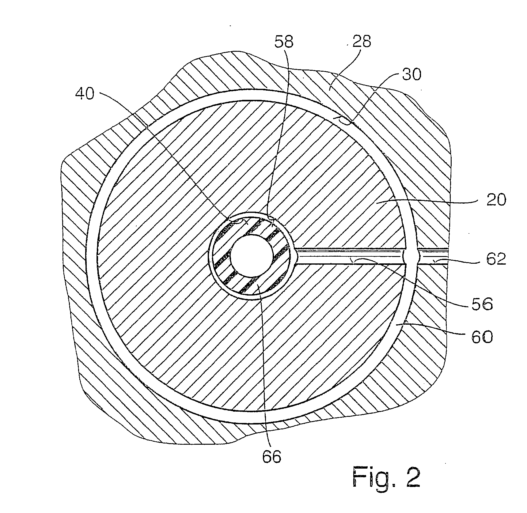
[0007] The device 10 has a mixing chamber body 20, in which a mixing chamber 22, explained in further detail hereinafter, is embodied, and a metering valve 24 that is connected to the mixing chamber body 20 and has a valve body 26. The mixing chamber body 20 and t...


PUM

PropertyMeasurementUnit
Diameteraaaaaaaaaa

Abstract

The device is a component of a system for posttreatment of the exhaust gas of a self-igniting internal combustion engine; by means of the mixture of reducing agent and air that it generates, the action of a reduction catalytic converter is improved. The device has a mixing chamber (22), into which reducing agent, via a reducing agent supply means controlled by a metering valve (24), and air, via an air supply means, can be introduced. The mixing chamber (22) is embodied in a mixing chamber body (20), with which a valve body (26) of the metering valve (24) is connected. The mixing chamber (22) discharges, toward the metering valve (24), into a connection stub (42), and the metering valve (24) has a valve member (74), which to control the reducing-agent/air mixture supply means into the mixing chamber (22) cooperates at least indirectly with the face end (43) of the connection stub (42) as a valve seat. The valve body (26) is screwed into a bore (38) of the mixing chamber body (20). The result is a simpler design of the device, with only a few components which are simple to assemble.

Description

PRIOR ART[0001] The invention is based on a device for generating a mixture of reducing agent and air as generically defined by the preamble to claim 1.[0002] One such device is known from the literature: Dieselmotor-Management, Vieweg Verlag, 2nd Ed., 1998, page 31. This device is part of a system for posttreatment of exhaust gases of internal combustion engines, in particular self-igniting internal combustion engines. By the addition of a reducing agent to the exhaust gas, the effectiveness of a reduction catalytic converter for reducing nitrogen oxides in the exhaust gas can be improved. The device has a mixing chamber, into which reducing agent can be introduced through a reducing agent supply connection, controlled by a metering valve, and air can be introduced via an air supply connection. Such devices often have a complicated design, with many components, and with a large structural size. The metering valve is embodied as a separate component unit that is connected to the dev...

Claims


Application Information

Patent Timeline
IPC IPC(8): B01D53/90F01N3/08B01D53/94F01N3/20
CPCB01D53/90B01D53/9431F01N3/2066Y02T10/24F01N2610/08F01N2610/1453F01N2610/02Y10T137/87676Y10T137/8766Y02T10/12
Inventor MAYER, HANSPETER
Owner ROBERT BOSCH GMBH
Why Eureka
Try Eureka