Transmission power control method, radio communication system, base station and mobile station

a technology of radio communication system and transmission power control, which is applied in the direction of power management, transmission monitoring, wireless communication, etc., can solve the problems of communication errors, power observed, and lower throughput than a method without transmission power control in the transmitter

Inactive Publication Date: 2004-06-03
GOOGLE LLC
View PDF8 Cites 40 Cited by
  • Summary
  • Abstract
  • Description
  • Claims
  • Application Information

AI Technical Summary

Problems solved by technology

In this case, the receiver observes signals other than required signals as interference signals, so that the required signals do not satisfy the required SIR when the received power of the signals other than the required signals is larger than the received power of the required signals.
However, the radio communication system adopting the second control method has a problem in that the transmitter determines the transmission power of the signals based on the interference power observed in the receiver, so that the interference power when the transmission power was determined often differs from the interference power during actual transmission of packet signals which are burst-type traffic.
Thus, the required signals do not satisfy the required SIR in the receiver and there is a high possibility of the occurrence of communication errors when signals such as the packet signals are transmitted and the interference power observed in the receiver changes during a short period.
In other words, the second control method has a problem in that there is a possibility of causing lower throughput than a method without transmission power control in the transmitter.
However, this method has a problem in that the determined transmission power becomes greater than necessary, so as to cause a reduction in channel-efficiency.
The method has a problem in that the required SIR and the predetermined margin are controlled based on the ratio (dB) between the received power and the interference power in the receiver, thus making it susceptible to burst-type interference signals (for example, packet signals) when the interference power is small.
On the other hand, the first control method h

Method used


Image

  • Transmission power control method, radio communication system, base station and mobile station
  • Transmission power control method, radio communication system, base station and mobile station
  • Transmission power control method, radio communication system, base station and mobile station

Examples


Embodiment Construction

>

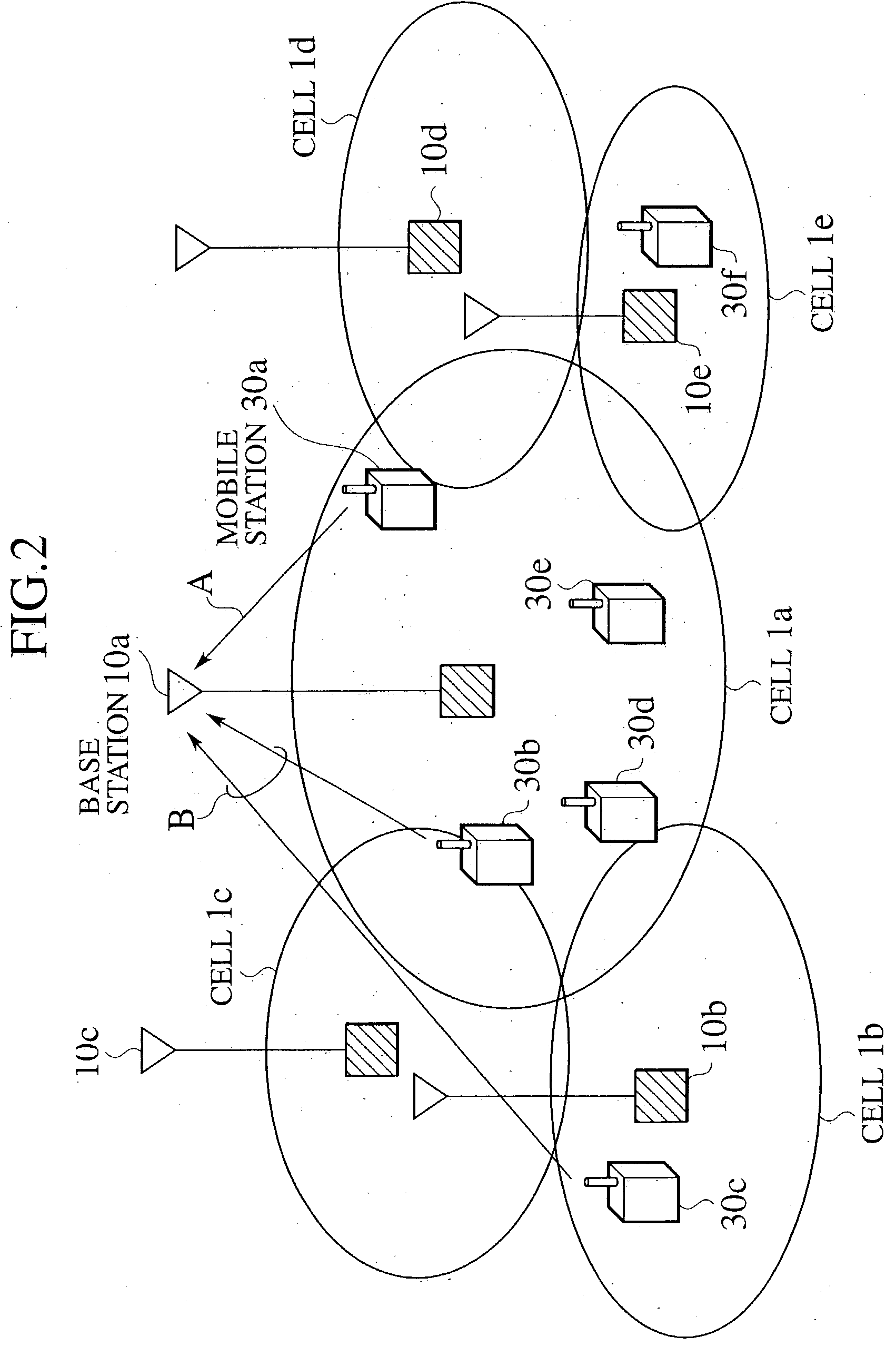
[0049] FIG. 2 shows an entire configuration of the radio communication system according to the first embodiment of the present invention.

[0050] As shown in FIG. 2, the radio communication system has a plurality of cells (radio zones) 1a to 1e which are formed by a plurality of base stations 10a to 10e. A plurality of mobile stations 30a to 30f exist in the respective cells 1a to 1e.

[0051] As shown in FIG. 2, the radio communication system according to the first embodiment allows radio communications between the base station 10 and the plurality of mobile stations 30 via CDMA radio channels.

[0052] As shown in FIG. 2, when the mobile station 30a existing in the cell 1a transmits packet signals A to the base station 10a which forms a cell 1a, packet signals B which are transmitted from the mobile station 30b existing in the cell 1a and the mobile station 30c existing in the cell 1b can be interference signals to the packet signals A.

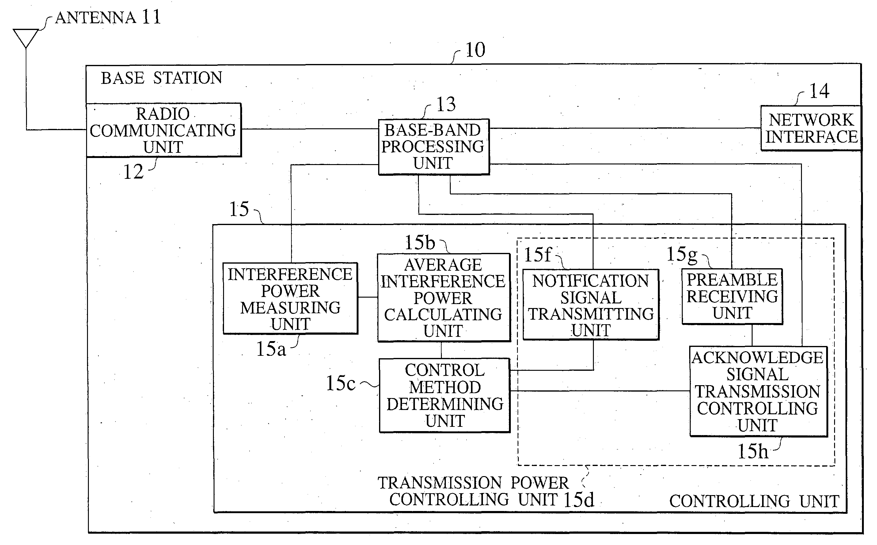
[0053] FIG. 3 shows functional blocks of the base st...


PUM


Abstract

The object of the present invention is to provide a transmission power control method which enables the resolution of problems in a first control method for keeping the received power of packet signals in upstream radio channels constant and a second control method for keeping the SIR constant. The present invention relates to the transmission power control method for controlling the transmission power control of packet signals transmitted from a mobile station 30 via an upstream radio channel. The method comprises a step of measuring the traffic volume of the packet signals and a step of switching between the first control method and the second control method.

Description

[0001] This application is based upon and claims the benefit of priority from the prior Japanese Patent Application No. P2002-215764, filed on Jul. 24, 2002; the entire contents of which are incorporated herein by reference.[0002] 1. Field of the Invention[0003] The present invention relates to a transmission power control method for controlling the transmission power of packet signals to be transmitted from a mobile station via an upstream radio channel, in a radio communication system for allowing radio communications between a base station and a plurality of mobile stations via code division multiple access (CDMA) radio channels. The present invention also relates to a radio communication system, a base station and a mobile station which can be used in the above transmission power control method.[0004] 2. Description of the Related Art[0005] The conventional radio communication system for transmitting signals via CDMA radio channels differs from the radio communication systems fo...

Claims


Application Information

Patent Timeline
IPC IPC(8): H04B7/26H04B7/005H04B17/345H04L1/16H04W16/14H04W24/00H04W52/04H04W52/14H04W52/24H04W52/34H04W52/50H04W76/02H04W80/06H04W92/10
CPCH04L1/1607H04W16/14H04W24/00H04W92/10H04W52/243H04W52/34H04W52/50H04W52/146
Inventor KAYAMA, HIDETOSHICHEN, LANUMEDA, NARUMI
Owner GOOGLE LLC
Why Eureka
Try Eureka