Tibial resurfacing system

a resurfacing and tibial technology, applied in the field of orthopaedic joint replacement, can solve the problems of individual joint replacement surgery, high cost, and high cost, and achieve the effect of reducing the risk of fractur

Active Publication Date: 2004-06-03
ARTHROSURFACE
View PDF16 Cites 129 Cited by
  • Summary
  • Abstract
  • Description
  • Claims
  • Application Information

AI Technical Summary

Problems solved by technology

It has now become well accepted that treating this individual with a total joint arthroplasty (prosthetic) will be an effective way of relieving the symptoms of pain, but this younger patient will likely place demands on his prosthetic joint that will result in the rapid wear, loosening, and need for replacement of the implants.
In the natural knee, loads transmitted to the joint surfaces during normal activities such as running, walking, and jumping create harsh environments for the articular surface tissues.
The wear and degradation of these tissues is typically the endpoint, which creates symptoms of pain and eventually drives an individual to consider joint replacement surgery.
However, many structures and tissues in the joint as well as the musculature of the leg play a complex role in the distribution and management of the loads ultimately seen by the articular surfaces.
In prosthetic knee joints, one of the greatest causes of failure is based on wear debris of the tibial component.
Not only does this result in the wear of the tibial component but also produces small wear debris particles which stimulate osteolysis, inflammatory changes in neighboring tissues, and eventual loosening of the implant.
Mismatch of the surfaces or misalignment of the surfaces during surgical implantation will cause accelerated wear and early failure of the joint.
However, as a function of the complex mechanics of the knee, even in the event of perfect surgical matching and alignment of the two components, there are still articulations of the prosthetic joint that create very concentrated local or even point loads between the two components, which result in the creation of a shear particle from the UHMWPE surface.

Method used


Image

  • Tibial resurfacing system
  • Tibial resurfacing system
  • Tibial resurfacing system

Examples


Embodiment Construction

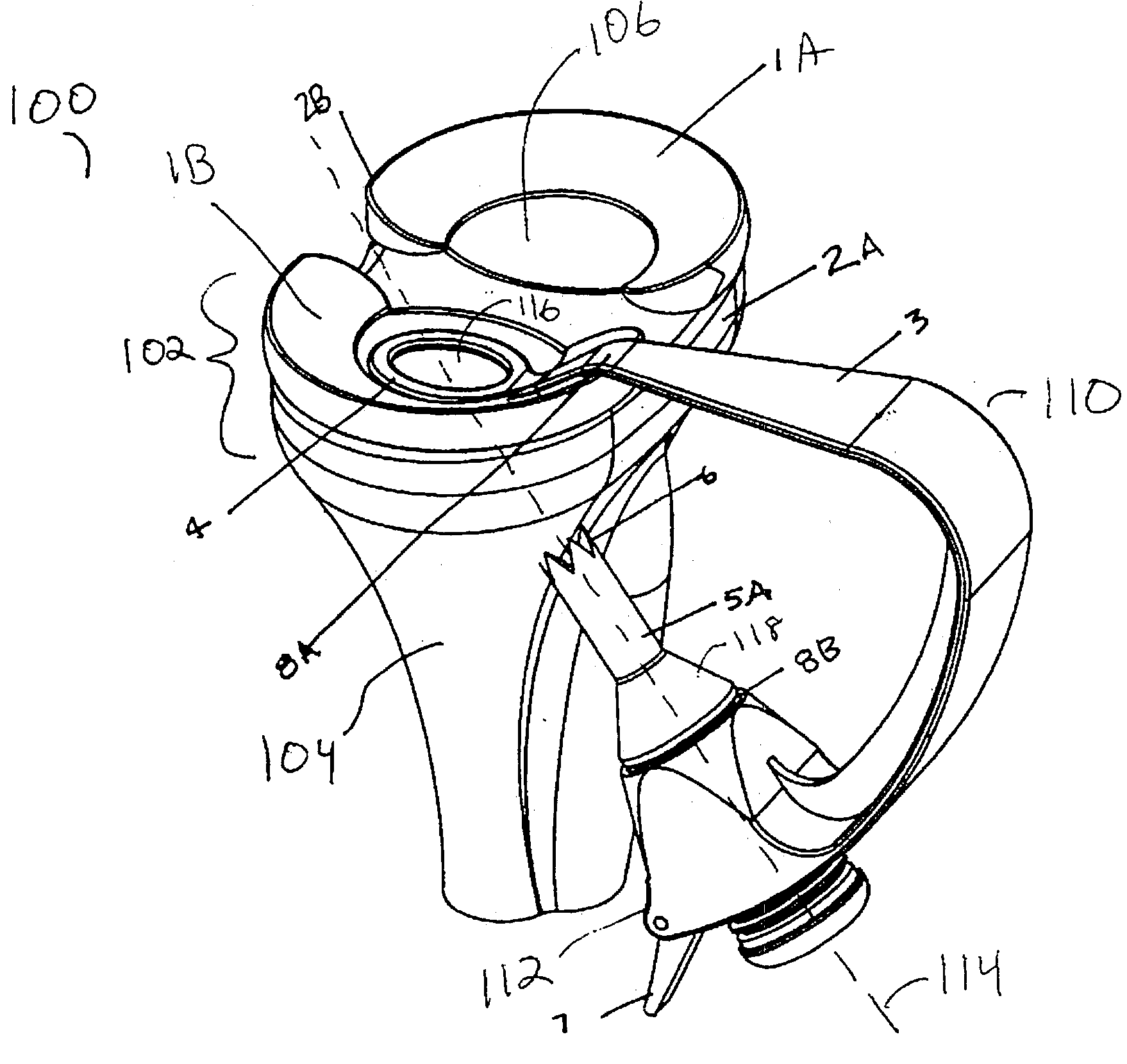
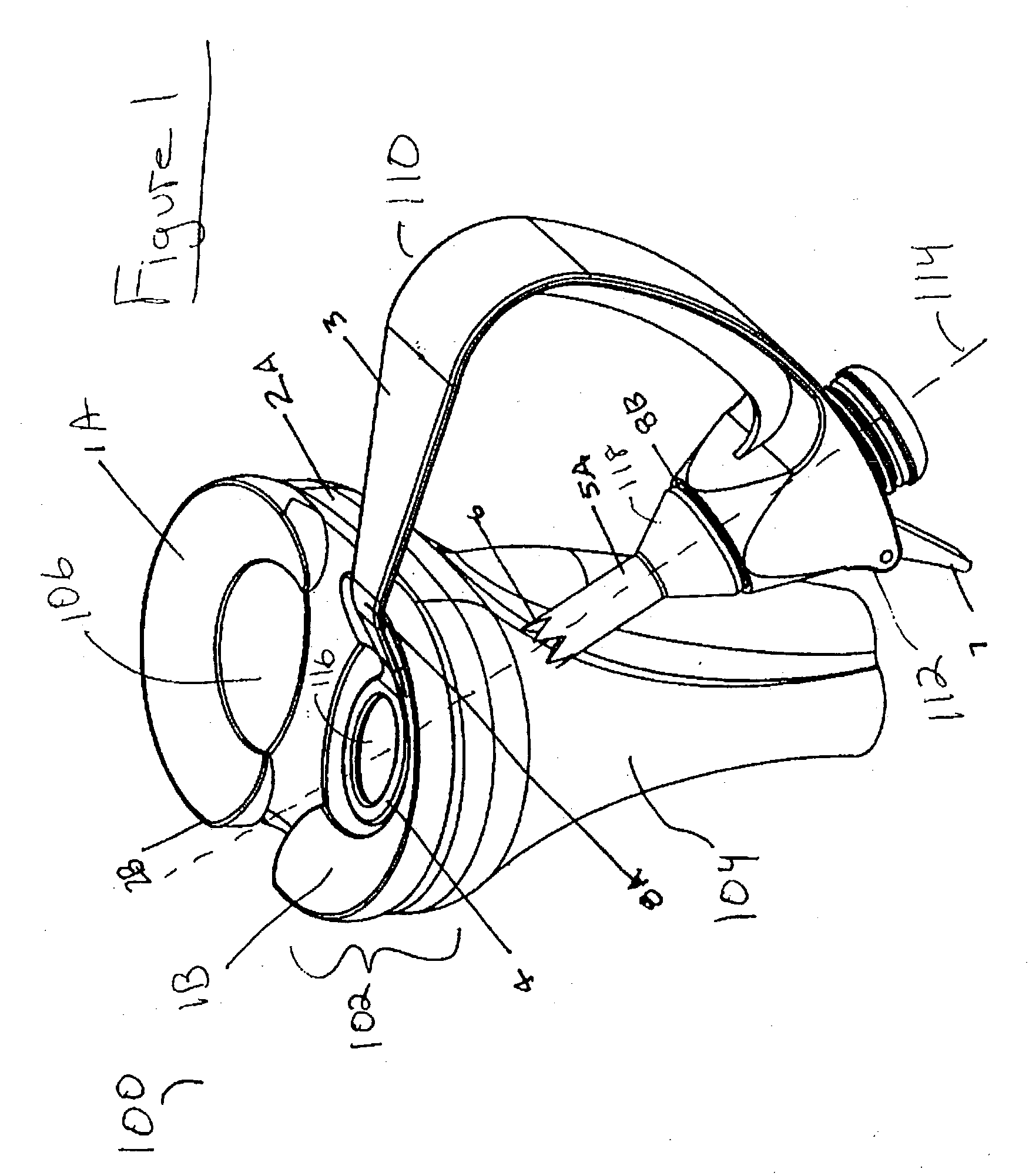
[0028] FIG. 1 is an in situ view 100 of one exemplary drill guide according to the present invention. This figure depicts the proximal portion 102 of the tibia as well as the distal tibia 104. The knee contains a meniscus 1A and 1B in both the lateral and medial compartments, respectively. The meniscus is connected to the superior tibial surface by way of an anterior 2A and posterior 2B bony attachment. The meniscus is otherwise relatively mobile and glides along the top of the tibia 104 in concert with and as a partial constraint to the femoral condyle (not shown, but well understood in the art).

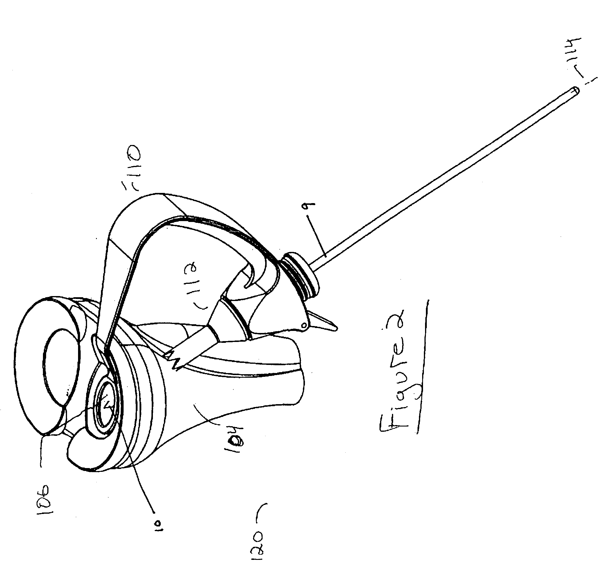
[0029] In one aspect of the present invention, a novel drill guide is provided. In one exemplary embodiment, a drill guide 110 is depicted in FIG. 1. The drill guide 110 of this exemplary embodiment generally includes a targeting ring 4, and angled boom 8A, a curved arm section 3 and a bore section 112. The targeting ring 4 may have a thickness that is narrow enough to be inserted between t...


PUM

PropertyMeasurementUnit
distanceaaaaaaaaaa
diameteraaaaaaaaaa
angleaaaaaaaaaa

Abstract

A tibial resurfacing system is provided that includes a drill guide, bone chisel and implant. In one aspect, the system includes a drill guide that includes a targeting ring that is shaped to be placed on the superior tibial surface and a bore section that is connected to the ring to create an axis through the tibia to the superior tibial surface in the vicinity of the targeting ring. The drill guide permits a drill pin and / or drill to be advanced through the tibia to the superior tibial surface. In another aspect, a bone chisel is provided that includes an elongated tubular structure having a first end and a bone-cutting end, and the bone-cutting end is terminated in a transverse angle thereby creating an elliptical bone-cutting face. In another aspect, an implant is provided that includes an angled bearing element formed of a cylindrical member having a first end and a second end. The first end is formed at an angle that creates an elliptical face of the first end, and the first end defines a load-bearing surface of an articular surface.

Description

1. FIELD OF THE INVENTION[0001] The present invention relates generally to the field of orthopedic joint replacement, and particularly, to the field of orthopedic joint replacement of the knee.2. BACKGROUND OF THE INVENTION[0002] In the field of orthopedic joint replacement of the knee, a relatively recent evolution of the art has resulted in prosthetics that require less removal of bone stock as the preparation for the implantation of the prosthetic devices. This trend in technique and prosthetic design is primarily aimed at creating more options for the orthopedic surgeon when challenged with treating a young active individual with joint disease. It has now become well accepted that treating this individual with a total joint arthroplasty (prosthetic) will be an effective way of relieving the symptoms of pain, but this younger patient will likely place demands on his prosthetic joint that will result in the rapid wear, loosening, and need for replacement of the implants.[0003] In ...

Claims


Application Information

Patent Timeline
Patent Type & Authority Applications(United States)
IPC IPC(8): A61B17/16A61B17/56A61B17/17A61F2/00A61F2/30A61F2/38A61L27/00
CPCA61B17/1604A61B17/1675A61B17/1764A61F2/30721A61F2/30749A61F2220/0033A61F2002/30354A61F2002/30604A61F2002/3085A61F2002/3895A61F2/389
Inventor EK, STEVEN
Owner ARTHROSURFACE
Why Eureka
Try Eureka