
Device for a respirator

a technology for respirators and devices, applied in respirators, intravenous devices, tracheal tubes, etc., can solve the problems of inability to operate the transport system, risk of bacterial contamination of the sterile lung region, and the inability to allow large or fast air movement of the endotracheal tub

Inactive Publication Date: 2004-06-10
ALORO MEDICAL
View PDF26 Cites 4 Cited by
  • Summary
  • Abstract
  • Description
  • Claims
  • Application Information

AI Technical Summary

Benefits of technology

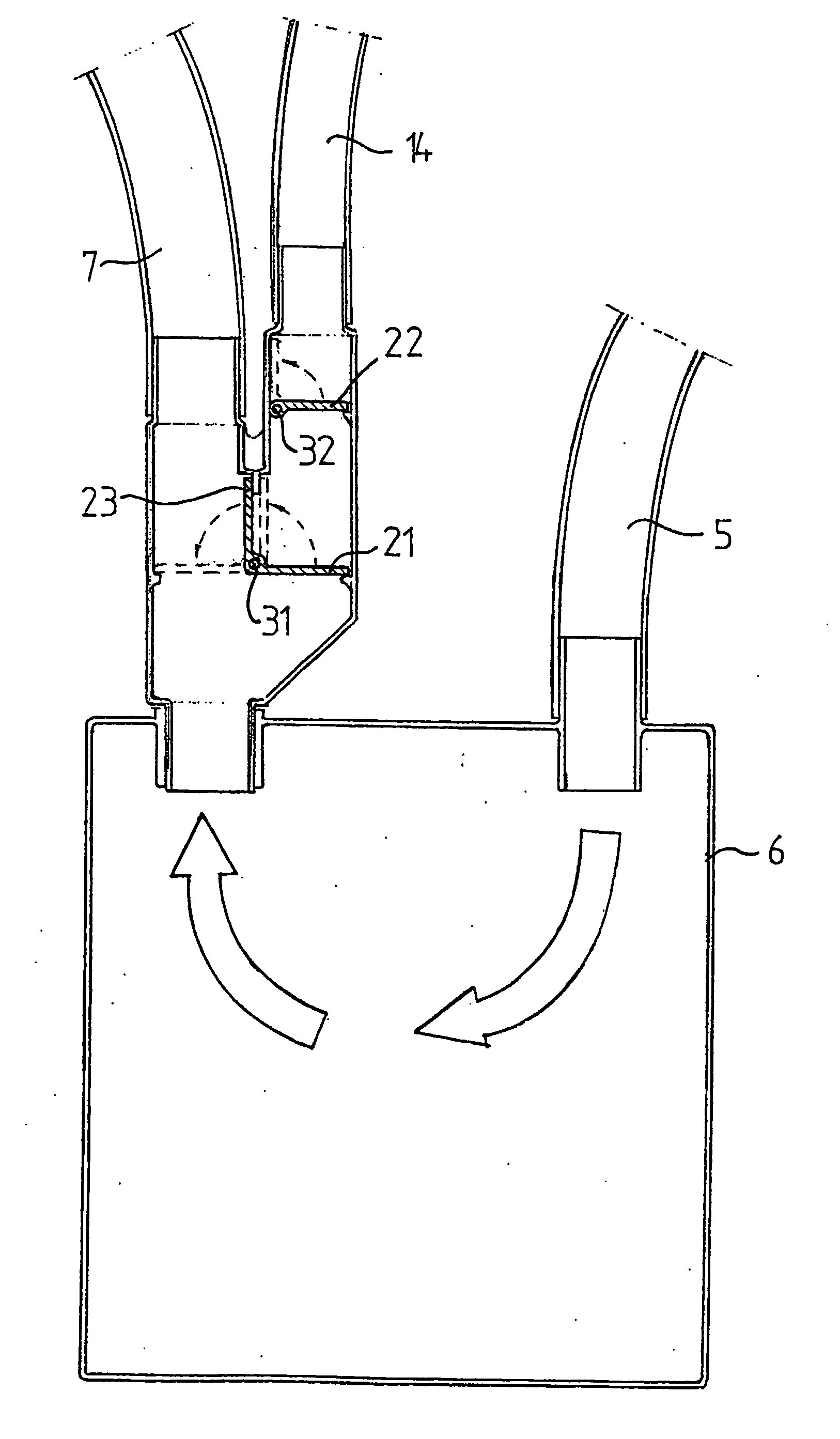
[0010] By means of the second passage, which extends between the pipe member and a source providing a sub-pressure, and the valve arrangement, which in an active position during a short period of time, is arranged to keep the second passage open, it is thus possible to apply instantaneously a temporary short sub-pressure in a passage, which leads the exhalation gas from the lungs. Such a sub-pressure provides a simulated cough reflex of the patient. This simulated cough reflex may contribute to an improved transport of secretions from the lungs and the trachea.
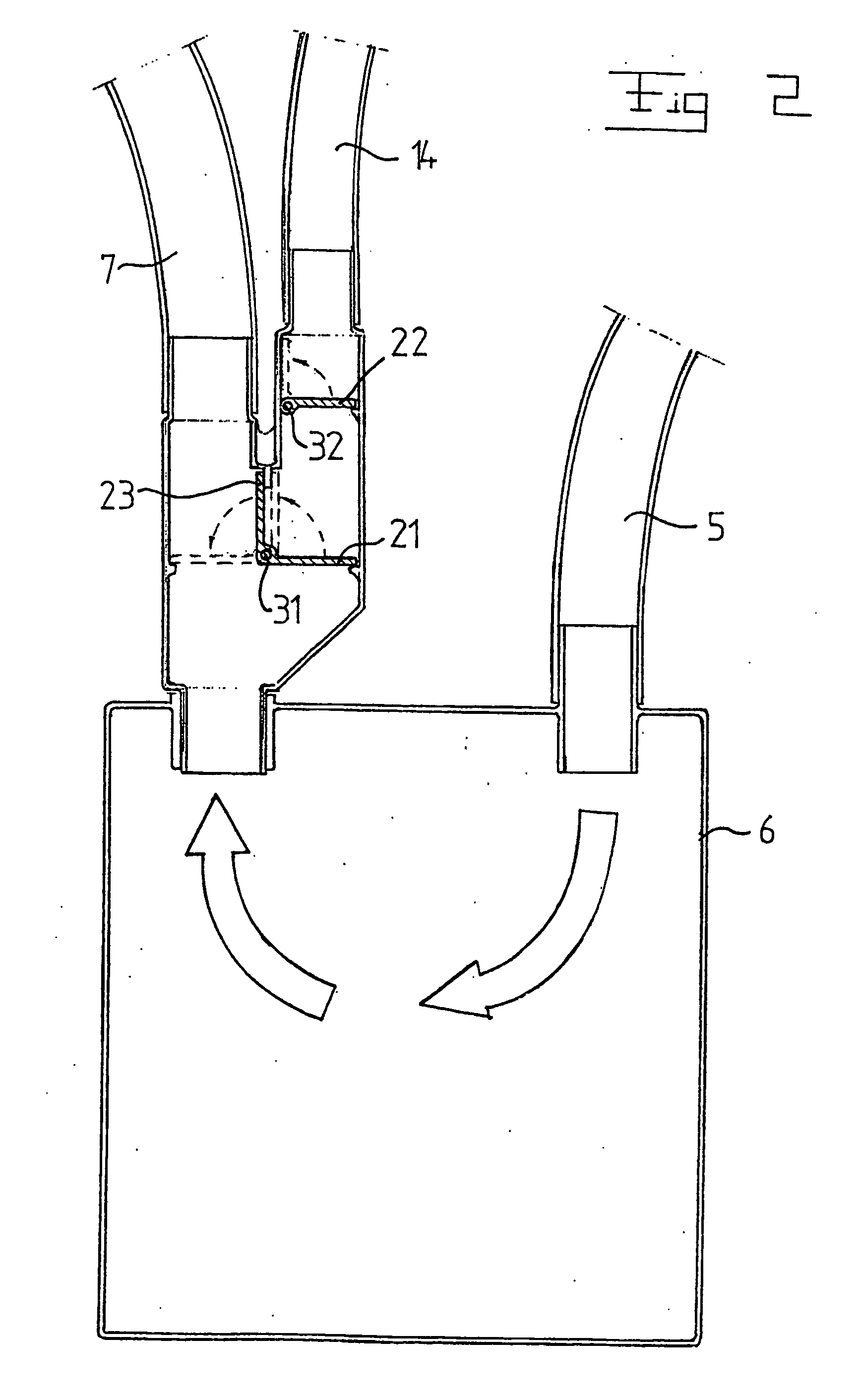
[0013] According a further embodiment of the invention, the valve arrangement includes a second valve, which is provided between the first valve and said source and which is arranged to be open in said active position and closed in said inactive normal position. By means of two such valves of the second passage, the security of the device may be improved. In order to be able to apply a sub-pressure it is required that both the first valve and the second valve are open, i.e. displaced from their closed normal positions.

Problems solved by technology

When a conventional endotracheal tube is attached in the trachea, this transport system can not any longer function.
Such a catheter suction is combined with a risk of bacterial contamination of the sterile lung region.
However, resistance from the endotracheal tube does not permit any large or fast air movements, which could contribute to forcing air and thus secretions outwards.
A powerful cough reflex may therefore lead to a spontaneous extubation, i.e. that the endotracheal tube is loosened and makes continued ventilation impossible.
In case of a great production of secretions, the second channel could possibly be blocked and thus prevent an efficient gas exchange.

Method used


Image

  • Device for a respirator
  • Device for a respirator
  • Device for a respirator

Examples


Embodiment Construction

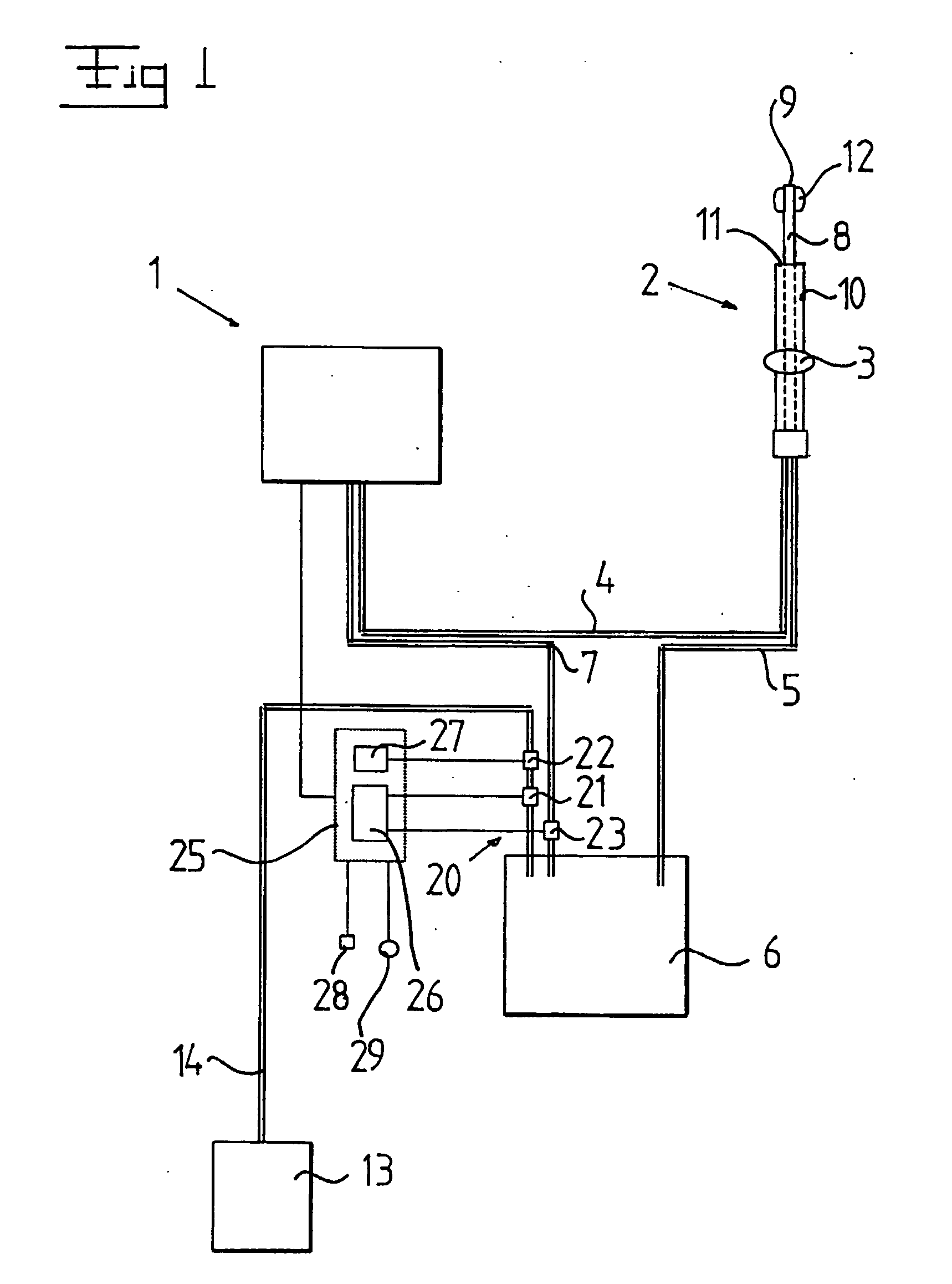
[0023] FIG. 1 discloses a respirator 1, which includes a pipe member 2, which is intended to be introduced into the trachea of a patient and which may be a so-called endotracheal tube. The pipe member 2 is arranged to be fixed in the trachea by means of a fixing member 3. The fixing member 3, which may be a so-called cuff, includes a swelling body, which is arranged to be expandable to sealing abutment against the inner wall of the trachea by the supply of a medium via a conduit (not disclosed).

[0024] The pipe member 2 is connected to the respirator 1 via a (third) passage in the form of a first transport conduit 4 for the supply of inlet gas or breathing gas to the lungs of the patient during a first state for the respirator 1. Furthermore, the pipe member 2 is connected to the respirator 1 via a (first) passage for the discharge of outlet gas or exhalation gas from the patient during a second state for the respirator 1. In the embodiment disclosed, this passage is formed by a seco...


PUM


Abstract

Then invention refers to a device for a respirator. A pipe member (2) is arranged to be intodruced into the tracheaof a patient. The respirator (1) is arranged to supply inhalation gas va the pipe member (2) to the lungs of the patient and to discharge exhalation gas via the pipe member (2) from the lungs of the patient. At least a first passage (5-7) connects the pipe member (2) to the respirator (1) and is at least arranged to permit discharge f he exhalation gas. A second passage (5, 6, 14) extends between the pipe member (2) and a source (13), which provides a sub-pressure. A third pasage connectsthe pipe member to the respirator and is arranged ot perment and supply of inhalation gas. A valve arrangement (20) is, in an active state during a short period of time, arranged to keep the second passage (5, 6, 14) open.

Description

THE BACKGROUND OF THE INVENTION AND PRIOR ART[0001] The present invention refers to a device for a respirator, which device includes a pipe member arranged to be introduced into the trachea of a patient and which is arranged to supply inhalation gas via the pipe member to the lungs of said patient during a first state and to discharge exhalation gas via the pipe member from the lungs of said patient during a second state.[0002] When a patient is treated by means of a respirator such a pipe member, a so-called endotracheal tube is used, which is a hose that is introduced into the trachea and attached in an airtight manner in the trachea by means of a fixing member, a so-called cuff. Ventilation takes place by supplying air to the lungs during inhalation whereas the exhalation takes place in a passive manner in that the thorax and the diaphragm compress the lungs. The trachea has a natural transport system for transporting secretions upwards. When a conventional endotracheal tube is a...

Claims


Application Information

Patent Timeline
IPC IPC(8): A61M1/00A61M16/04A61M16/20
CPCA61M1/0031A61M16/202A61M16/0465A61M16/0463A61M1/74
Inventor FLODIN, BJORN
Owner ALORO MEDICAL
Learn More