

Image display apparatus for displaying image in variable direction relative to viewer
a technology of image display and variable direction, applied in the field of image display apparatus, can solve the problem of not always a consistency between display directions in which different viewers are shown
- Summary
- Abstract
- Description
- Claims
- Application Information
AI Technical Summary
Problems solved by technology
Method used
Image

Examples
first embodiment
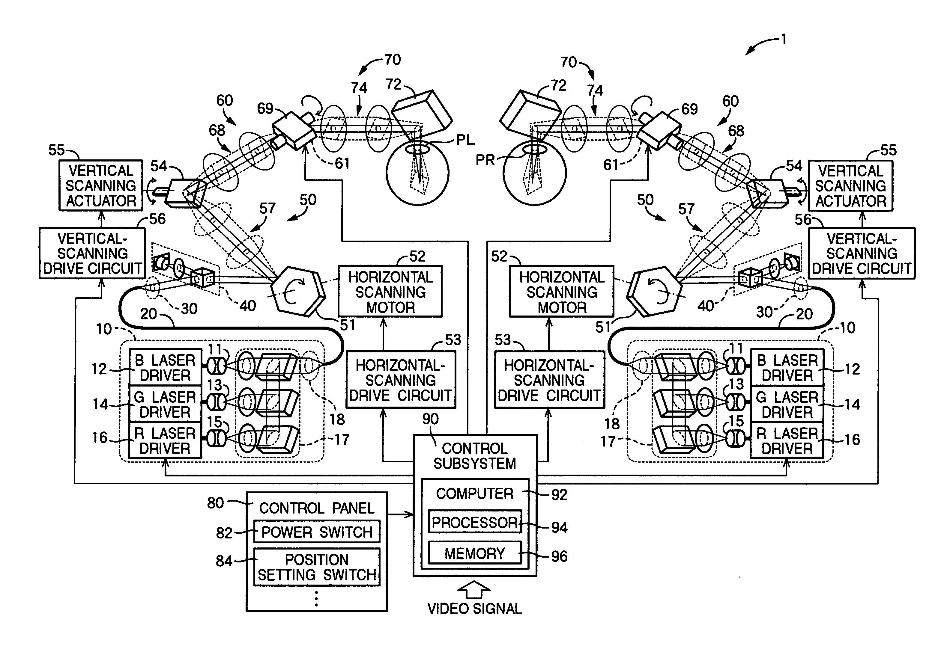
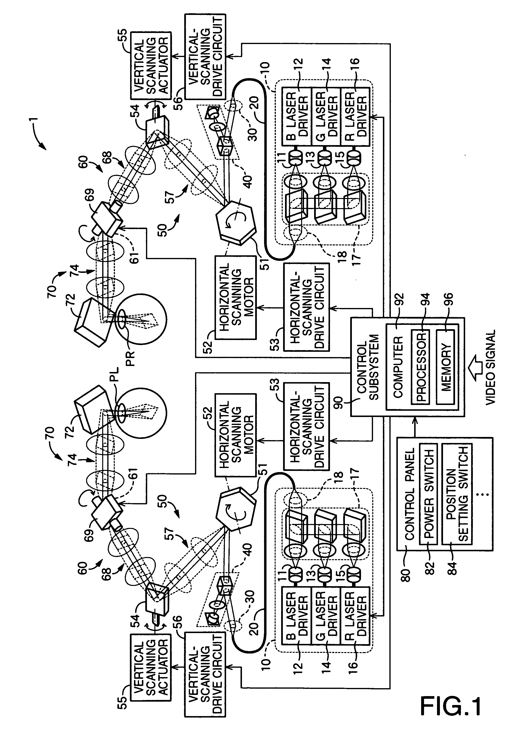
[0140] Referring first to FIG. 1, there is shown an image display apparatus 1 constructed according to the invention. The image display apparatus 1 is adapted to cause light beams to enter the pupils P (PR: the pupil of the viewer's right eye ER, PL: the pupil of the viewer's left eye EL) of a user of the image display apparatus 1, i. e., a viewer, and to project an image onto the viewer's retinas, for thereby permitting the viewer to perceive a virtual image in front of the pupils PR, PL. The image display apparatus 1 is called "retinal scanning display."
[0141] The image display apparatus 1 is equipped with a light-beam generating subsystem 10 for producing and outputting a light beam corresponding to an image to be displayed, i.e., for generating the light beam; and a collimating optical subsystem 30 for transforming the light beam which was output from the light-beam generating subsystem 10 and which passed through an optical fiber 20, into a parallel light.
[0142] The image displ...
second embodiment
[0236] Referring next to FIG. 7, there will be described a second embodiment of the present invention. Since the most of the elements used in the second embodiment correspond to those of the first embodiment, the corresponding elements will be identified by referring to the same reference numerals or titles, instead of explaining the corresponding elements in detail, while only the distinctive elements of the second embodiment will be explained in detail.
[0237] As shown in FIG. 7, an image display apparatus 2 constructed according to the present invention is equipped with, as with the first embodiment, the light-beam generator 10; the collimating optical subsystem 30; the curvature modulating subsystem 40; the scanning subsystem 50; the angle modifying subsystem 60; the light-beam guiding subsystem 70; the control panel 80; and the control subsystem 90.
[0238] The image display apparatus 2 is further furnished with a sight-line sensor 100 which is absent from the first embodiment. Th...
third embodiment
[0305] There will be next described a third embodiment of the present invention. Since the most of the elements used in the third embodiment correspond to those of the first embodiment, the corresponding elements will be identified by referring to the same reference numerals or titles, instead of explaining the corresponding elements in detail, while only the distinctive elements of the third embodiment will be explained in detail.
[0306] In the first embodiment, the angle modifying subsystem 60 is constructed to have both the angle modifying mirror 61 and the second relay optical system 68. Instead, in the present embodiment, the angle modifying subsystem 60 is constructed to use an optical element formed as a mirror in common with the scanning subsystem 50.
[0307] Referring to FIG. 11, an image display apparatus 3 constructed according to the present embodiment is illustrated as with FIG. 1. In the image display apparatus 3, the vertically modifying mechanism 62 and the horizontally...
PUM
 Abstract
Description
Claims
Application Information