Plunger needle for an intraocular lens injector

Active Publication Date: 2004-06-10
ASICO +1
View PDF9 Cites 44 Cited by
  • Summary
  • Abstract
  • Description
  • Claims
  • Application Information

AI Technical Summary

Problems solved by technology

In addition, measures must be taken to ensure that at no time does the lens move in an undesired way about the plunger tip and become stuck in the injector.
Inserting the lens without damage is made difficult by anchoring means, referred to as haptics, which may be present on the lens.
Since these anchoring means protrude from the folded lens, they can easily become st

Method used


Image

  • Plunger needle for an intraocular lens injector
  • Plunger needle for an intraocular lens injector
  • Plunger needle for an intraocular lens injector

Examples


Embodiment Construction

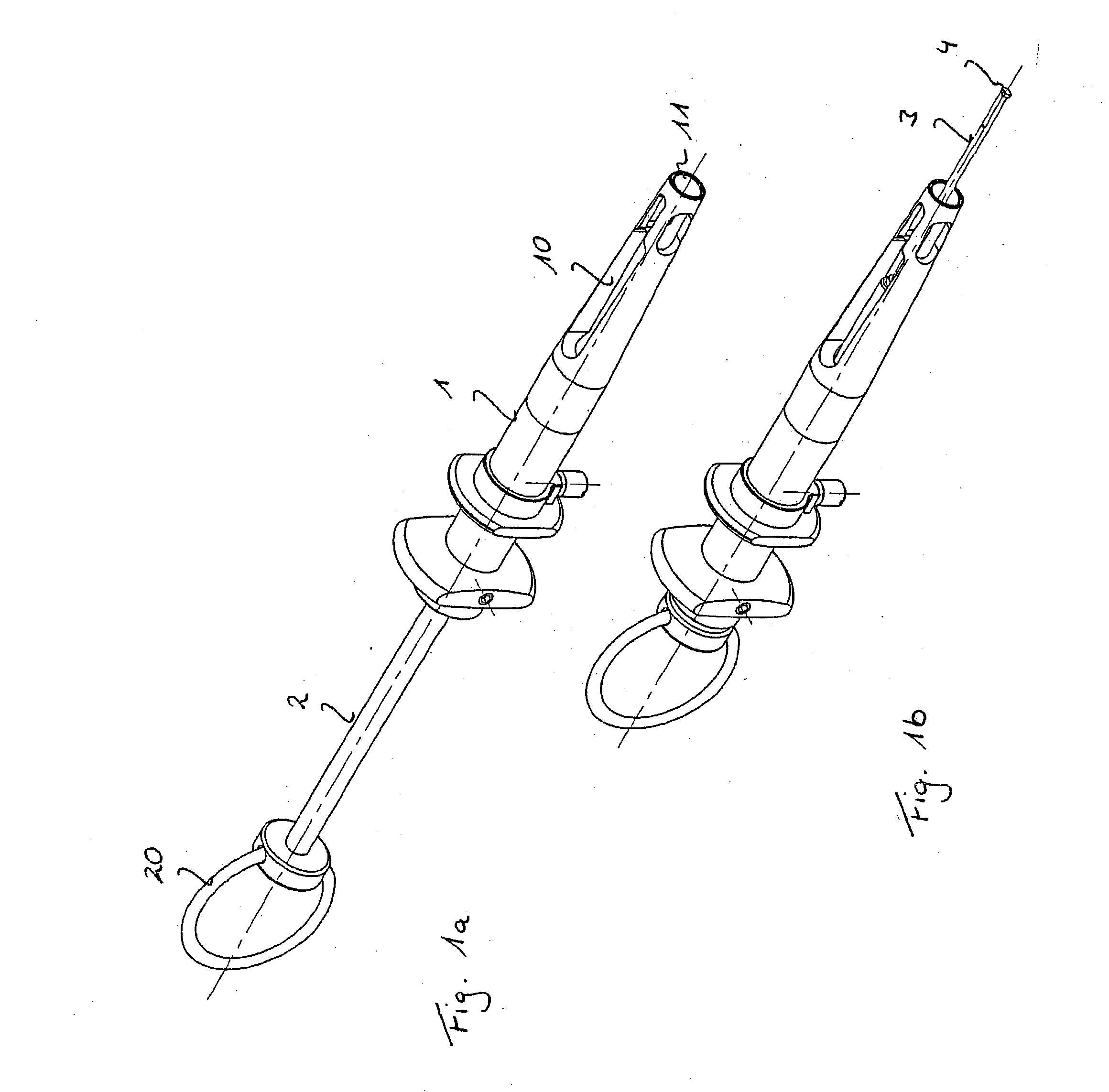
[0046] FIGS. 1a and 1b show an example of an intraocular injector. The embodiments of the plunger needle according to the invention which are described below can, however, also be used in other injectors, particularly the injectors which are standard today.

[0047] The injector has a sleeve-shaped grip body 1 through which a plunger passes. The plunger has a plunger rod 2 with a finger ring 20 arranged at its rear end, in particular for the thumb, and a plunger needle 3 arranged at its front end. The plunger needle 3 can be secured releasably on the plunger rod 2, in particular via a threaded connection.

[0048] The grip body has a lens holder 10 for receiving a lens (not shown here). The lens is usually inserted with a cartridge into the lens holder 10. The cartridge protrudes from the front end of the lens holder. The lens is pushed out of the cartridge by means of the plunger and injected into a patient's eye.

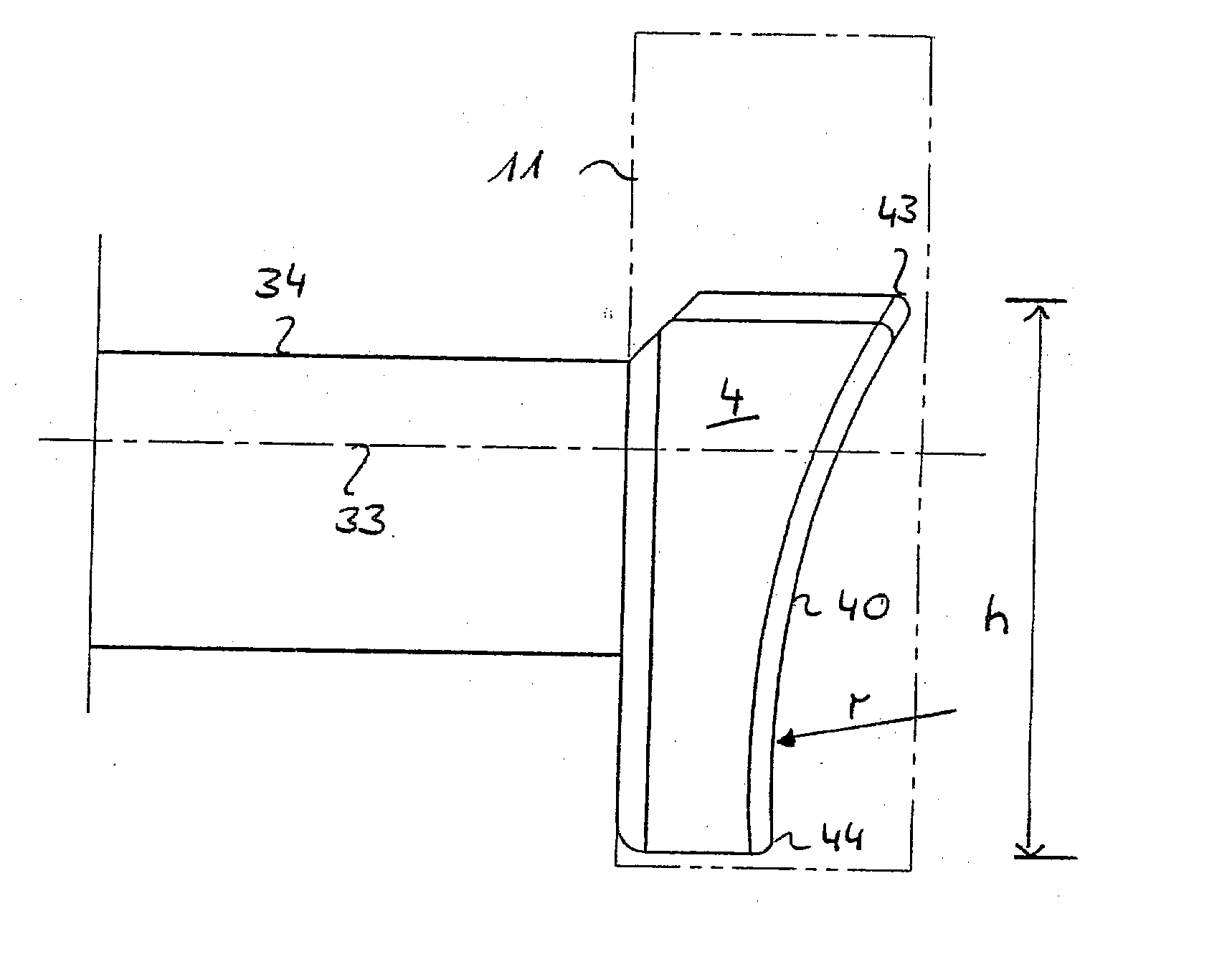
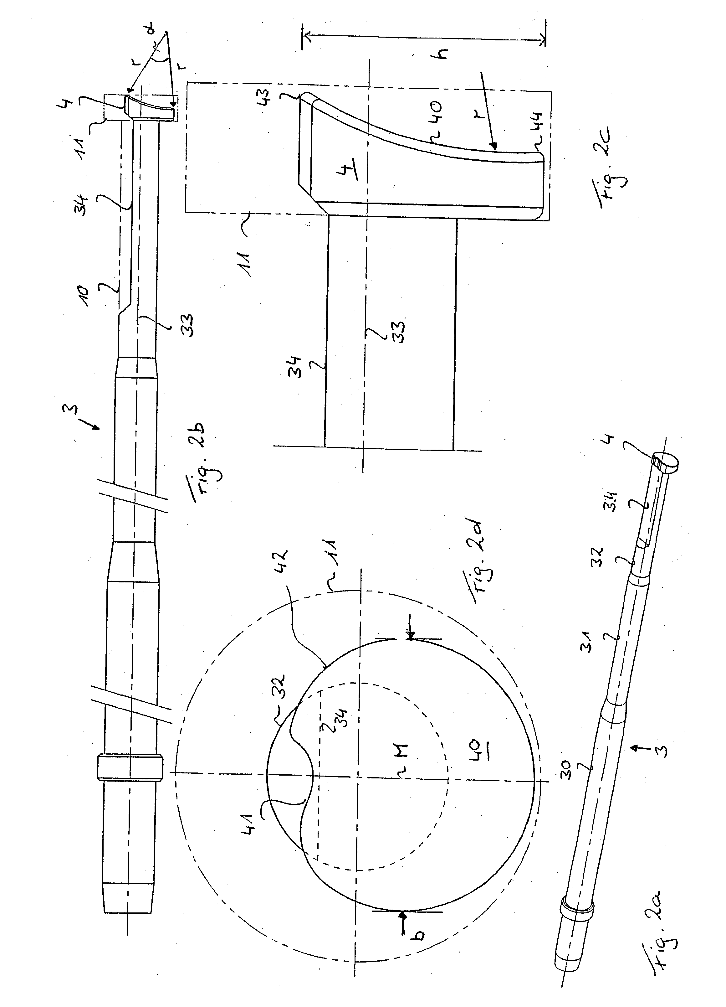
[0049] A first illustrative embodiment of a plunger needle 3 according to t...


PUM


Abstract

A plunger needle (3) for an intraocular lens injector has a plunger tip (4) with a contact area for making contact with a lens (L), the contact area being arranged in a front face (40) of the plunger tip (4), which is curved cylindrically. The plunger needle (3) according to the invention, with its specially configured plunger tip (3), permits reliable guiding of the lens (L) upon injection into an eye and prevents the lens (L) becoming stuck in the injector. It is also easy to produce.

Description

[0001] The invention relates to a plunger needle for an intraocular lens injector.PRIOR ART[0002] Opaque natural lenses can be replaced with artificial lenses called IOLs. In this procedure, the patient's opaque lens is first removed. The artificial lens is then fitted, either manually with the aid of forceps, or using an injector. This injector consists principally of a sleeve-shaped grip body with a lens holder and with a plunger which can be displaced in a guided manner in the grip body. The lens, packed in a cartridge in the folded state, is inserted into the lens holder. In the same way as in a syringe, the lens is injected through an opening into the eye. To do so, the plunger is either pushed forward in a straight line or is turned forward in a guided manner in a thread. The lens is able to unfold in the eye, the unfolding often being assisted by rotation of the plunger.[0003] Various injectors are known in the prior art. A list of the best known types is provided in the intr...

Claims


Application Information

Patent Timeline
IPC IPC(8): A61F9/007A61F2/16
CPCA61F2/1664
Inventor MEYER, ROLF
Owner ASICO
Why Eureka
Try Eureka