
Card printing devices

a printing device and card printing technology, applied in the direction of printing, other printing devices, article separation, etc., can solve the problems of insufficient number of cards to be produced, old personalisation methods, simple inability to reproduce photographs or similar images, etc., to achieve smooth sequential feeding of cards into the printing portion of the machine, the effect of improving the reliability of card separation

Inactive Publication Date: 2004-06-17
NBS TECH
View PDF10 Cites 5 Cited by
  • Summary
  • Abstract
  • Description
  • Claims
  • Application Information

AI Technical Summary

Benefits of technology

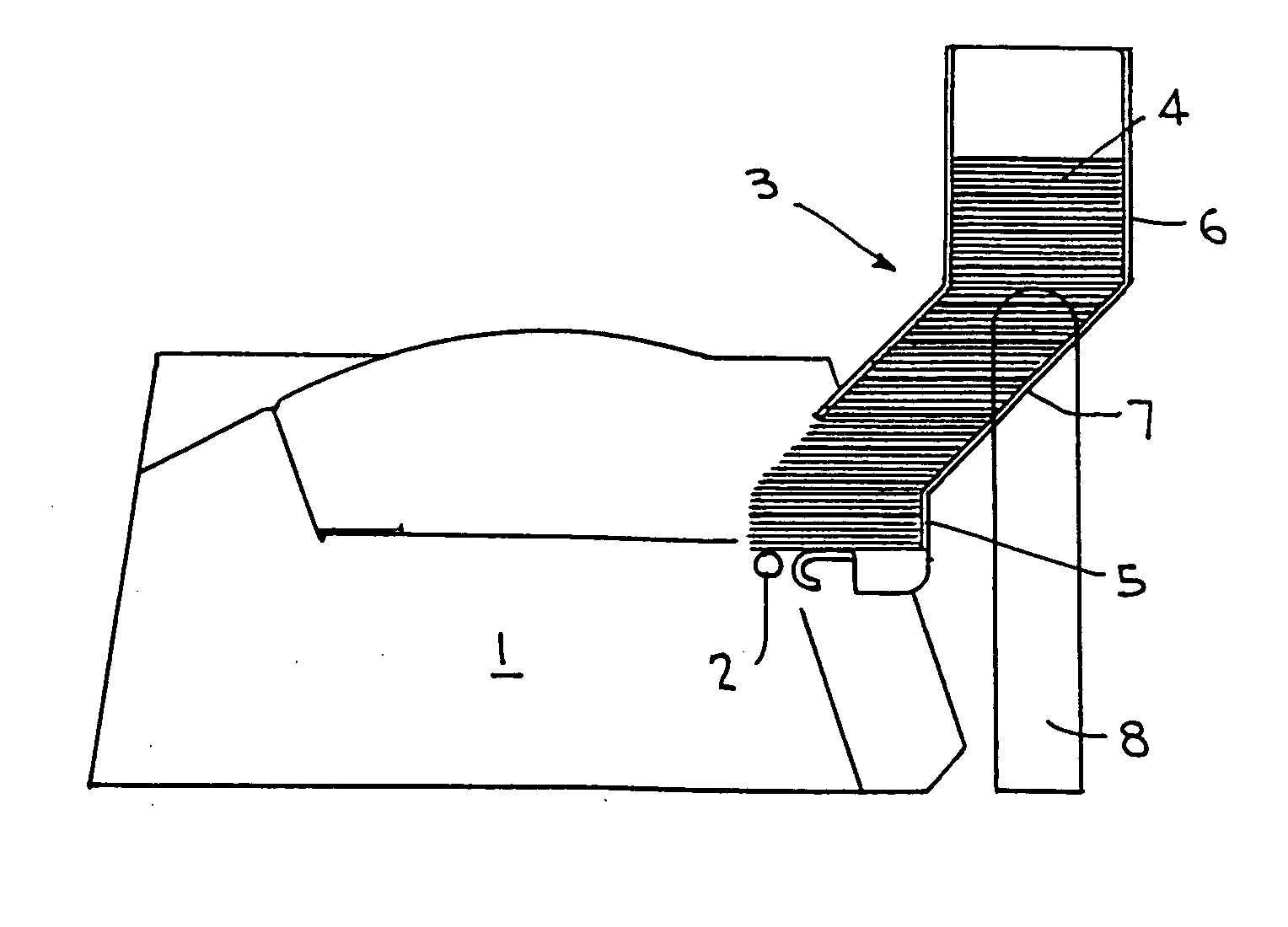
[0009] We have now found that simple card feeder mechanisms may be retained while enabling the automated printing of a stack of cards by providing that the apparatus has means for removing cards simultaneously from the base of a stack of such cards, and wherein the stack is, at least in part, inclined to the vertical. The degree of inclination is preferably at least 15.degree., and it may be as much as 45.degree. or even more. In any event, the inclination of the stack seems to have the effect of reducing the direct downward pressure on the lowermost card in the stack, enabling that card to be more simply and more reliably separated from the card above it. The inclination of the stack may be achieved by suitable design of the input hopper.
[0011] The floor of the input hopper is usually substantially horizontal, though it may be slightly inclined from the horizontal, depending upon the precise engineering detail of the in-feed mechanism. We have found that if the dimensions of the in-feed hopper, in a plane parallel to the floor of the hopper, in at least one portion of the in-feed hopper, are such as to incline the cards successively as they travel down the hopper at an angle which differs from the angle of the floor and accordingly the angle of the lowermost card, the reliability of card separation and smooth sequential feeding of the cards into the printing portion of the machine is much enhanced, believed to be at least in part due to the downward biasing of the lowermost card in the stack preferentially at the end towards the feed roller. This angular difference seems to act as a valuable pre-separating feature as the cards travel down the input hopper in the stack towards the in-feed area of the machine. This is usually simplest achieved by making a portion of the hopper, either in one of the generally inclined portions or one of the vertical portions, slightly less than the dimension of the card so that the card has to tip or tilt a little as it passes through that section.

Problems solved by technology

Old methods of personalising, e.g. credit and charge cards such as embossing, while satisfactory within certain constraints, simply are not apt to reproduce a photograph or similar image.
A problem arises in connection with such apparatus where the numbers of cards to be produced are insufficient to justify the expense of mass production apparatus, but too many for comfortable, simple, manual processing.
Many such materials have a tendency to "stick together", particularly in a stack of unprinted cards where there is not even the printing to assist separation of the cards one from another.
If it is, the pressure of the stack on the lowermost card renders it difficult to remove the card without the use of positively engaging card-shifting pusher members or the like; the usual frictional engagement with a rubbery drive wheel is insufficient to overcome the forces, both of friction and so-called `stiction`, which act on the bottom card.
Pre-treating the cards to reduce friction between them and the tendency to `stick` also adds to the expense, and there is a particular difficulty in the sense that many coatings which might notionally be applied to such cards to make them slide over one another with greater ease would also make the card surface more difficult to print on, thus undermining the very process which the card blanks are to undergo.

Method used


Image

  • Card printing devices
  • Card printing devices
  • Card printing devices

Examples


Embodiment Construction

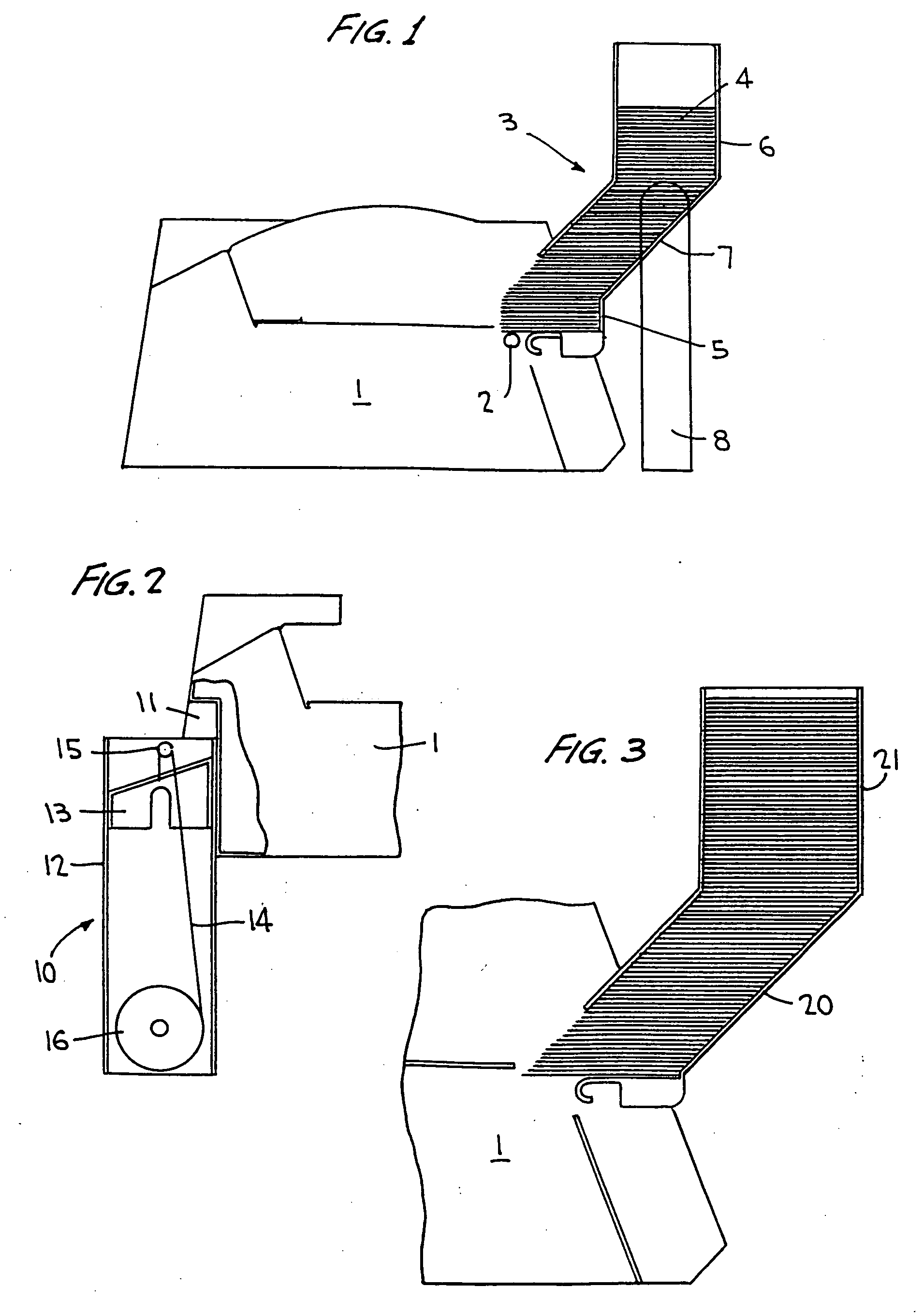
[0012] The invention is further described by way of example only with reference to the accompanying drawings in which:

[0013] FIG. 1 shows a diagrammatic side view of a card printer device having an input hopper in accordance with the present invention.

[0014] FIG. 2 is a schematic side view of the apparatus of the present invention showing a detail of a preferred outlet stack for the device;

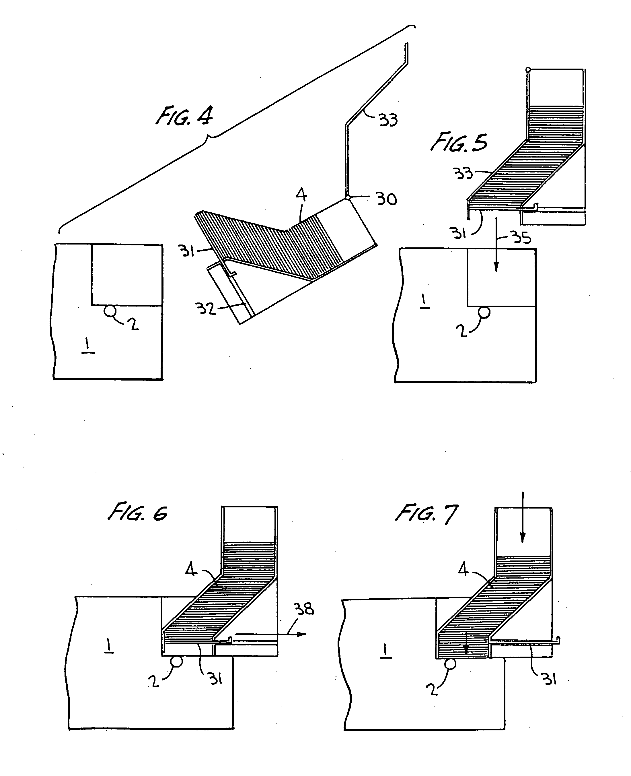
[0015] FIG. 3 is a diagrammatic side view showing an alternative input hopper design, and

[0016] FIGS. 4 to 7 show diagrammatically the loading and placement on a printer of a further variant hopper design.

[0017] Referring to FIG. 1, this shows in side view schematically a known card printer 1. This is drawn simply as the outline of the printer casing itself, the internal workings being unrelated to the present invention save for a driveable in-feed roller 2, the position of which is indicated diagrammatically to the right of the printer.

[0018] On the right hand side, the printer 1 carries a hopper...


PUM


Abstract

Card printing apparatus, for example, for printing identification cards, pass cards and the like generally comes with a relatively restricted size card input hopper. The number of cards that can be processed in a single operation is accordingly limited. The capacity for a single run of card printing can be materially increased without leading to card feed problems because of the increased pressure at the bottom of a stack of cards by arranging that at least part of the in-feed hopper is inclined away from the vertical. In order to maintain the footprint of the printer relatively small, the hopper preferably has two vertical sections and an intermediate inclined section.

Description

[0001] This invention relates to card printing devices.BACKGROUND TO THE INVENTION[0002] In recent years, the use of small rectangular pieces of plastics for identification and validation of all sorts of types of financial and other transactions has become ubiquitous. From the early days of embossed so-called charge cards or credit cards, which were carried by a relatively small proportion of the population, such cards are now used across a very wide spectrum and for purposes other than validating financial transactions.[0003] Although the items in question are universally referred to as "cards", generally speaking, they consist not of card, but of a plastics material. They may be composed of a single rectangular sheet of uniform such material, or they may have, for example, a sandwich or layered construction. In either case, there is a necessity for the card to carry certain common information, i.e. information which will be in common with other cards from the same issuer, as well ...

Claims


Application Information

Patent Timeline
Patent Type & Authority Applications(United States)
IPC IPC(8): B65H1/04
CPCB65H2701/1914B65H1/04
Inventor DAWSON, CHRIS
Owner NBS TECH
Learn More