Fault indicator capactive power source

a power source and fault indicator technology, applied in the direction of line-transmission details, safety/protection circuits, instruments, etc., can solve the problems of short operating life of fault indicators, inability to diagnose current surges without equipment, and failure to meet the needs of technicians, etc., to achieve the effect of increasing charge capacity

Inactive Publication Date: 2012-06-14
THOMAS KIRK
View PDF2 Cites 25 Cited by
  • Summary
  • Abstract
  • Description
  • Claims
  • Application Information

AI Technical Summary

Benefits of technology

[0018]An advantage of the present invention, where the fault indicator has a larger charge capacity by using a supercapacitor as opposed to a battery, is that the fault indicator can now use an LED display and other power consuming features that previously led to problems. The longer life expectancy of the fault indicator provides more reliability. Also, the fault indicator can now use a brighter display making the fault status more visible. Another advantage is that the fault indicator can accommodate changes through both hardware and firmware, as opposed to just hardware.
[0019]The foregoing, and other features and advantages of the invention, will be apparent from the following, more particular description of the preferred embodiments of the invention, the accompanying drawings, and the claims.

Problems solved by technology

Malfunctions in power distribution systems are often accompanied by transient current surges in certain locations of the system.
However, because the current surge may have only lasted a short time, hence a transient current surge, the technician would not be able to diagnose the current surges without equipment that recorded the occurrence of these surges.
Of these two means of indicating a faulted or normal circuit, the LED display is preferred by many technicians because of its high visibility, however, these fault indicators have the shortest operating lives of all fault indicators due to their relatively high energy consumption, when operating the LED display, and their relatively low energy capacity batteries.
Generally, there are high costs associated with the manufacturing of fault circuit indicators (FCI's).
This overabundance of model-specific hardware coupled with the excessive component count results in high manufacturing costs.

Method used


Image

  • Fault indicator capactive power source
  • Fault indicator capactive power source
  • Fault indicator capactive power source

Examples


Embodiment Construction

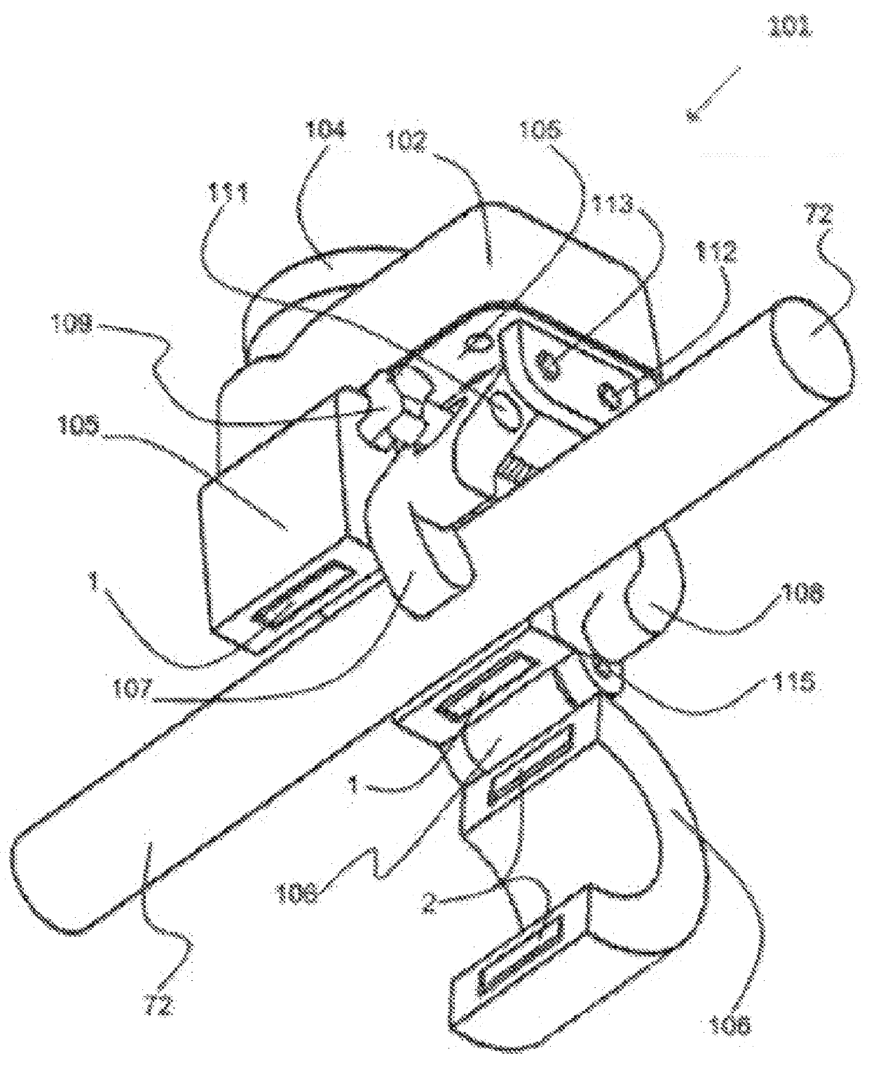
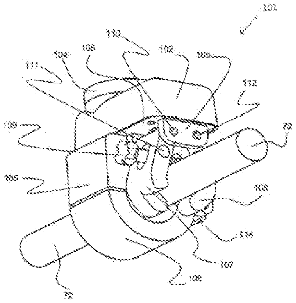
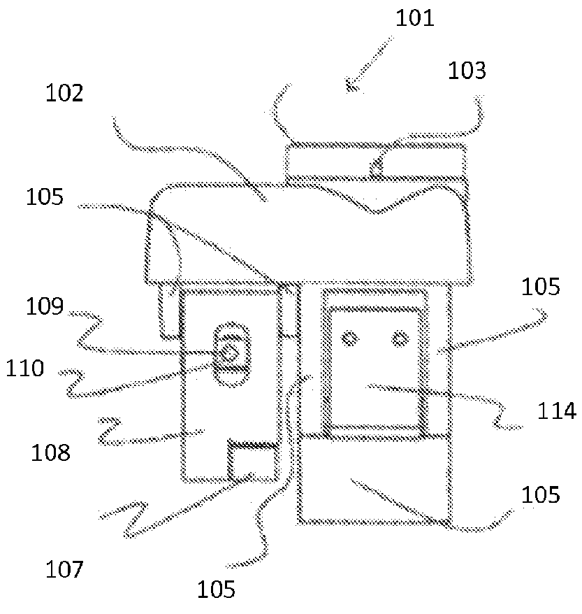
[0027]Further features and advantages of the invention, as well as the structure and operation of various embodiments of the invention, are described in detail below with reference to the accompanying FIGS. 1-11, wherein like reference numerals refer to like elements. Although the invention is described as implemented via a supercapacitor, one of ordinary skill in the art appreciates that other types of rechargeable capacitive power sources may be implemented. Further, although the capacitive power source uses a power line to power a fault indicator, the capacitive power source can also power many other electrical devices as well (e.g., a camera, wireless communication, etc.).

[0028]The present invention is direct to a fault indicator powered by a capacitive power source. The power source can be an inductive power supply that can easily and safely attach to a high voltage transmission line for retrieving low voltage, AC or DC power. The inductive power supply can utilize an inductor,...


PUM


Abstract

The present invention provides, in at least one embodiment, a fault indicator powered by a capacitive power source. The capacitive power source can be a charged capacitor which can be charged by an electrostatic field and an electromagnetic field around a power line being monitored. The charged capacitor can be an electrochemical double-layer capacitor, a supercapacitor, or an ultracapacitor. These capacitors provide superior energy storage compared to conventional battery power sources.

Description

CROSS REFERENCE TO RELATED APPLICATIONS[0001]This continuation-in-part application claims the benefit of U.S. patent application Ser. No. 12 / 698,953, filed on Feb. 2, 2010, and entitled “High Voltage to Low Voltage Inductive Power Supply with Current Sensor,” and the application claims priority under 35 U.S.C. §119(e) to U.S. Provisional Application No. 61 / 410,766, filed Nov. 5, 2010, and entitled “Microprocessor Controlled Fault Indicator Module Powered by Ultra Capacitor, Double Layer Capacitor, or Super Capacitor,” the disclosures of which are hereby incorporated by reference in their entirety.BACKGROUND OF THE INVENTION[0002]1. Field of Invention[0003]The invention relates generally to an electric power distribution system in a wide geographic area and more particularly, to systems and methods of powering a device that detects and records fault conditions at various locations.[0004]2. Description of Related Art[0005]An electric power distribution system delivers electricity from...

Claims


Application Information

Patent Timeline
Patent Type & Authority Applications(United States)
IPC IPC(8): G01R31/02
CPCH02J7/025H01F38/30G01R1/22H02J7/00304H02J50/10
Inventor THOMAS, KIRK
Owner THOMAS KIRK
Why Eureka
Try Eureka