

Handle arrangement for a power tool
- Summary
- Abstract
- Description
- Claims
- Application Information
AI Technical Summary
Benefits of technology
Problems solved by technology
Method used
Image

Examples
Embodiment Construction
Cross Reference To Related Applications
[0001] The present application is a continuation-in-part of co-pending Application Serial No. 10 / 011,251, filed December 3, 2001.
Background of Invention
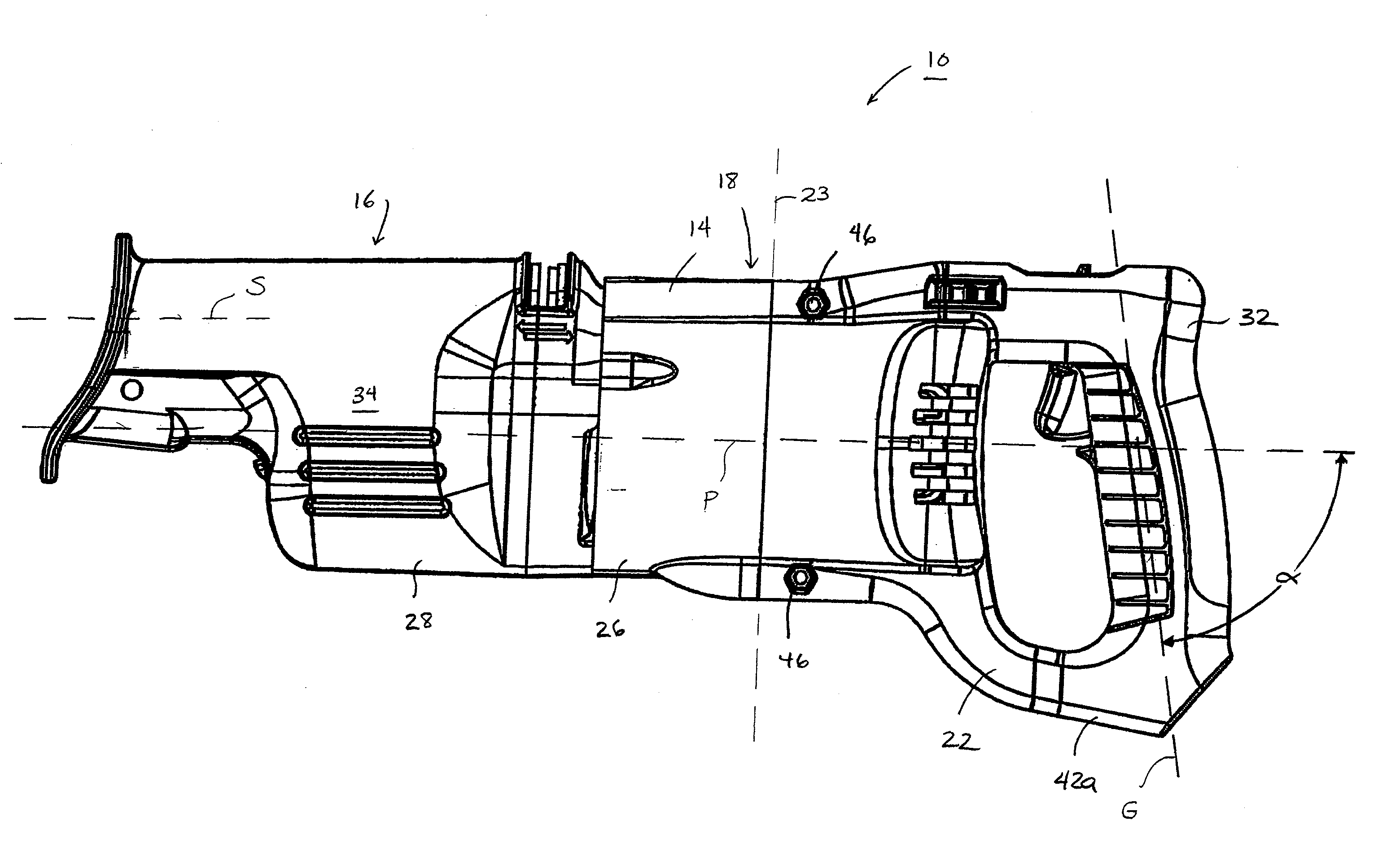
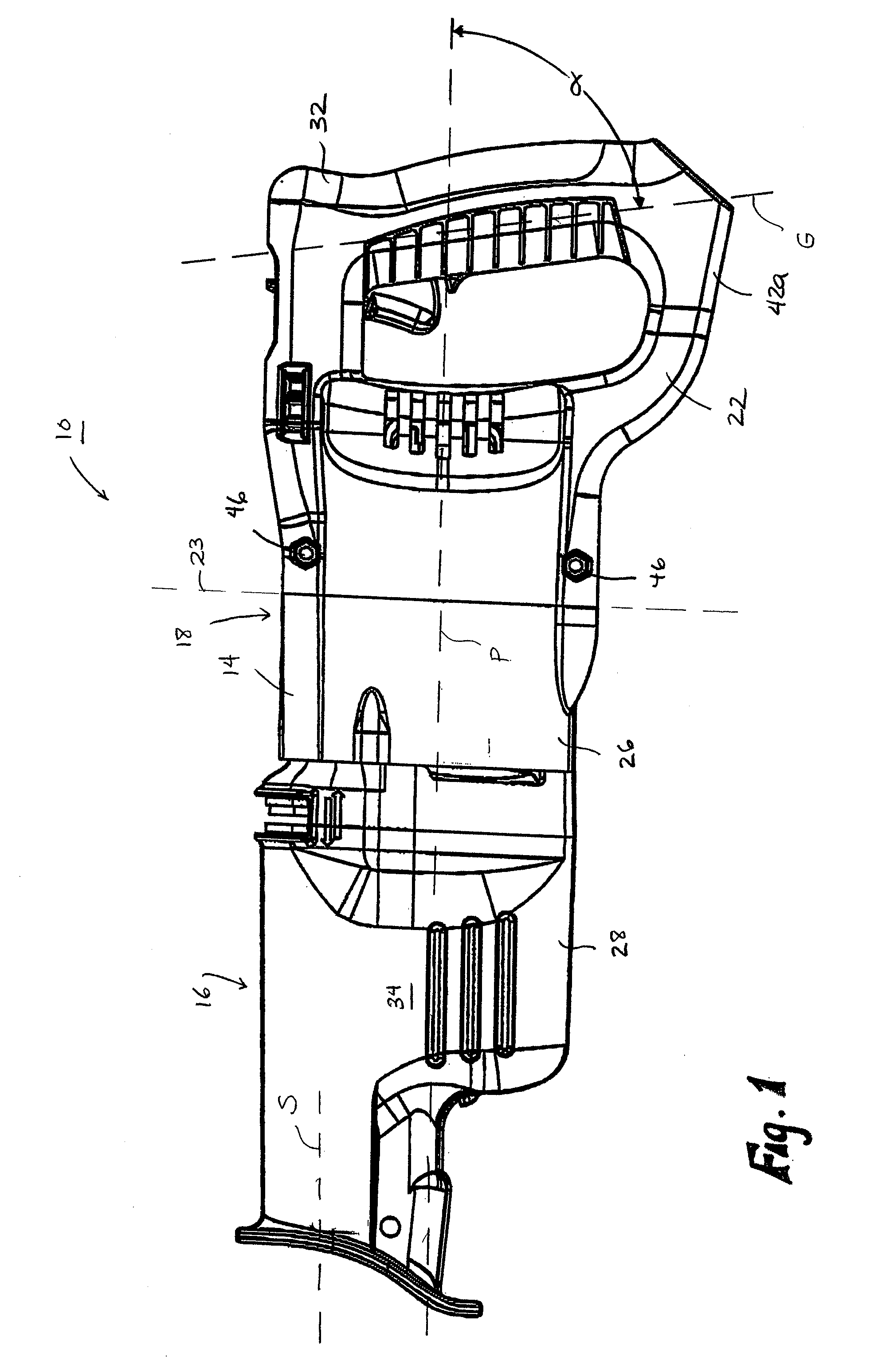
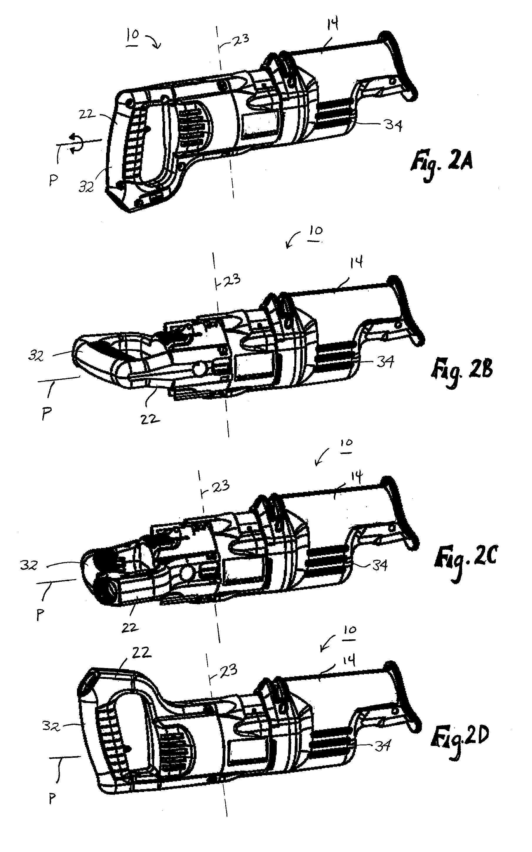
[0002] The present invention relates to power tools and, more particularly, to a handle arrangement for a power tool, such as a reciprocating saw.
[0003] A power tool, such as a reciprocating saw, generally includes a housing supporting a motor and a drive mechanism. The motor and the drive mechanism operate to drive a spindle and a tool element supported by the spindle. In a typical reciprocating saw, a main operator's handle is integrally formed with the rearward portion of the housing. Generally, the fixed-handle reciprocating saw is gripped by the operator with one hand on the main operator's handle and a second hand on a forward portion of the housing.
Summary of Invention
[0004] In some cutting operations, the operator may prefer a different handle position than the position in which the hand...
PUM
| Property | Measurement | Unit |
|---|---|---|
| Angle | aaaaa | aaaaa |
| Angle | aaaaa | aaaaa |
| Angle | aaaaa | aaaaa |
Abstract
Description
Claims
Application Information