Gas uniformizing device for PECVD (Plasma Enhanced Chemical Vapor Deposition) system

A gas device and air-distribution plate technology, which is applied in gaseous chemical plating, metal material coating process, coating and other directions, can solve the problem of uneven air distribution in the chamber, and achieve uniform air distribution, good control, and guarantee. The effect of uniformity

Inactive Publication Date: 2014-05-07
刘键
View PDF4 Cites 6 Cited by
  • Summary
  • Abstract
  • Description
  • Claims
  • Application Information

AI Technical Summary

Problems solved by technology

However, due to the existence of the lower electrode, the air outlet is generally not locate

Method used


Image

  • Gas uniformizing device for PECVD (Plasma Enhanced Chemical Vapor Deposition) system
  • Gas uniformizing device for PECVD (Plasma Enhanced Chemical Vapor Deposition) system
  • Gas uniformizing device for PECVD (Plasma Enhanced Chemical Vapor Deposition) system

Examples


Embodiment 1

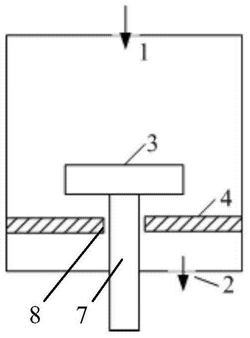
[0014] like figure 1 As shown, the present embodiment provides a uniform gas device for a PECVD system. The chamber of the PECVD system is provided with a substrate table 3 and a support rod 7 for supporting the substrate table. The first air distribution plate 4 below 3, the first air distribution plate 4 is a disc-shaped structure, and the outer edge of the first air distribution plate is closely attached to the inner wall of the chamber; the middle of the first air distribution plate 4 is provided with The ventilation hole 8, the support rod 7 is located in the ventilation hole 8, the ventilation hole 8 and the support rod 7 are arranged concentrically, the diameter of the ventilation hole 8 is larger than the diameter of the support rod 7, and the gap between the ventilation hole 8 and the support rod 7 is 1mm~20mm . The material of the first air distribution plate is stainless steel, aluminum or PTFE. The first air-distribution plate 4 can be a whole disc, can also be f...

Embodiment 2

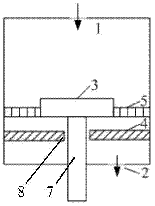
[0017] like figure 2 shown in figure 1 On the basis of , the air-distribution device also includes a second air-distribution plate 5, the second air-distribution plate 5 is arranged between the substrate table 3 and the inner wall of the chamber, and the second air-distribution plate 5 is connected to the substrate table 3 and the cavity respectively. The inner walls of the chamber fit snugly. According to actual needs, the second air distribution plate 5 can be selected from a single-layer air distribution plate or a multi-layer air distribution plate with evenly distributed ventilation holes.

[0018] The gas enters the chamber from the air inlet 1 of the chamber, passes through the second air distribution plate 5 and the first air distribution plate 4 in turn, and flows in the direction of the air outlet 2; the second air distribution plate 5 and the first air distribution plate The combination of 4 makes the effect of evenly distributing the airflow in the chamber bette...

Embodiment 3

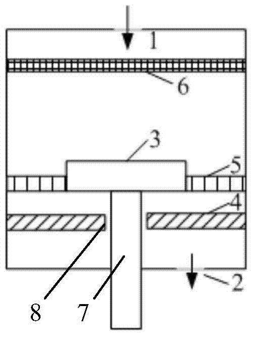
[0020] like image 3 shown in figure 2 On the basis of , the air distribution device also includes a third air distribution plate 6 , the third air distribution plate 6 is arranged above the substrate stage 3 , and the third air distribution plate 6 is closely attached to the inner wall of the chamber. According to actual needs, the third air distribution plate 6 can be selected from a single-layer air distribution plate or a multi-layer air distribution plate with evenly distributed ventilation holes. The third air distribution plate except image 3 The shown structure may also be a cylindrical structure with ventilation holes or a hollow annular structure with ventilation holes, which is directly communicated with the air inlet 1 .

[0021] The gas enters the chamber from the air inlet 1 of the chamber, passes through the third air distribution plate 6, the second air distribution plate 5 and the first air distribution plate 4 in sequence, and flows in the direction of th...


PUM


Abstract

The invention relates to the technical field of semiconductors, and particularly relates to a gas uniformizing device for a PECVD (Plasma Enhanced Chemical Vapor Deposition) system. The gas uniformizing device comprises a first gas uniformizing disc which is arranged below a substrate table, wherein the first gas uniformizing disc is of a disc-shaped structure, and the outer edge of the first gas uniformizing disc is tightly glued to the inner wall of a cavity; an air vent is formed in the middle of the first gas uniformizing disc, a supporting rod of the substrate table is located in the air vent, and the diameter of the vent hole is larger than that of the supporting rod. The first gas uniformizing disc in the uniformizing device provided by the invention is arranged below the substrate table, and gas flows towards an air outlet from a gap between the first gas uniformizing disc and the supporting rod so as to control gas flow in the lower half cavity very well, so that the distribution of the gas flow in the whole cavity is relatively uniform, and the uniformity of a deposition thin film is ensured.

Description

technical field [0001] The invention relates to the technical field of semiconductors, in particular to a uniform gas device used in a PECVD system. Background technique [0002] Thin film preparation is an important part of the semiconductor manufacturing process. According to the different adsorption and desorption properties, thin film deposition can generally be divided into physical vapor deposition (PVD) and chemical vapor deposition (CVD). Also includes atmospheric pressure chemical vapor deposition (APCVD), low temperature chemical vapor deposition (LPCVD) and plasma enhanced chemical vapor deposition (PECVD). Among them, PECVD is widely used in the preparation of various functional layers of semiconductor devices due to its low deposition temperature, easy control of film composition and thickness, good uniformity, good repeatability and excellent step coverage, such as barrier layers in CMOS devices, silicon Passivation layer of solar cells, flexible thin film en...

Claims


Application Information

Patent Timeline
IPC IPC(8): C23C16/513C23C16/455
Inventor 刘键刘杰
Owner 刘键
Why Eureka
Try Eureka