Flat tape cable separator

Inactive Publication Date: 2004-06-24
GENERAL CABLE TECH CORP
View PDF12 Cites 56 Cited by
  • Summary
  • Abstract
  • Description
  • Claims
  • Application Information

AI Technical Summary

Benefits of technology

0009] The present invention is directed to a high speed electrical data cable having a series of twisted pair conductors lying adjacent to one another and separated by a plurality of flat tape separators. Preferably, the electrical cable has four twisted pairs wrapped in an insulation jacket and separated with two or four flat tape separato

Problems solved by technology

Also, the tape separators are relatively small, thin objects havi

Method used


Image

  • Flat tape cable separator
  • Flat tape cable separator
  • Flat tape cable separator

Examples


Embodiment Construction

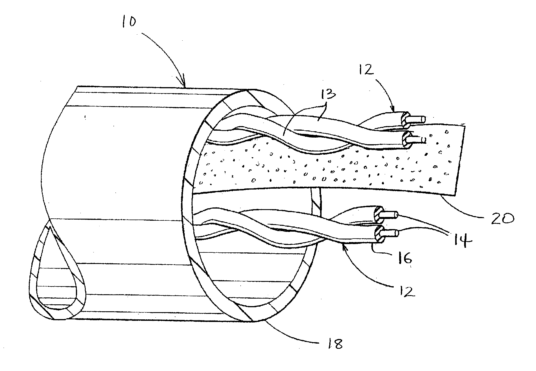
is now given with reference to FIGS. 1-4. Although the embodiments shown in the figures are directed towards electrical data cables, the concepts and inventive principles contained herein are applicable to other types of cables. Additionally, the embodiments shown in the figures contain four pairs of twisted electrical conductors (twisted pairs), but it should be understood that the invention contemplates using any number of twisted pairs.

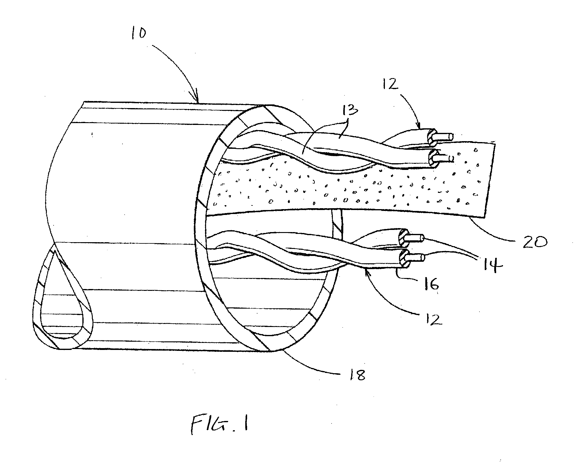
[0015] FIG. 1 shows a perspective view of an electrical high speed data cable 10 having a plurality of electrical twisted pair conductors 12. Each twisted pair 12 is made up of two conductors 13 that are twisted around each other along their longitudinal length. Each conductor 13 includes a conductive core 14, usually copper or other highly electrically conductive metal, surrounded by an insulative covering 16. A jacket 18 wraps around the twisted pairs 12 to form the single electrical cable 10.

[0016] FIG. 1 only shows two twisted pairs and a singl...


PUM


Abstract

The present invention is directed to a high speed electrical data cable having a plurality of twisted pair conductors lying adjacent to one another and separated by at least two flat tape separators. In the preferred embodiment, the electrical cable has four twisted pairs wrapped in an insulation jacket and separated with four flat tape separators. The tape separators are made of a plastic foam material having a low dielectric constant to reduce the crosstalk between adjacent twisted pairs and consequently, improve the cable's electrical performance. The plastic foam material is also highly flexible, providing the data cable with a high degree of flexibility and workability.

Description

[0001] The present invention is directed to a data communications cable having twisted pairs of electrical conductors separated by flat planar tapes that reduce the amount of crosstalk and improve the electrical performance of the data cable.[0002] High speed data communications cables that use pairs of twisted electrical conductors ("twisted pairs") are well known in the art. A single electrical cable often uses several twisted pairs which are closely spaced together and have a layer of outer insulation wrapped around them. Unfortunately, the close proximity of the twisted pairs encourages electrical energy transfer from one twisted pair to another, which is commonly referred to as crosstalk.[0003] One method of addressing the problem of crosstalk is to increase the spacing between twisted pairs by altering the twist lay or direction of twist of adjacent twisted pairs. A twisted pair is made up of two electrical conductors that are twisted around each other along their longitudinal...

Claims


Application Information

Patent Timeline
IPC IPC(8): H01B11/04
CPCH01B11/04
Inventor AUGUSTINE, KEVINSHACKELFORD, AMYDAVIES, BRAD
Owner GENERAL CABLE TECH CORP
Why Eureka
Try Eureka