
Display device and electronic apparatus

a technology of electronic equipment and display device, which is applied in the direction of lighting and heating equipment, electric apparatus casings/cabinets/drawers, instruments, etc., can solve the problems of difficult to thin the casing, the application of liquid crystal display device equipped with a backlight is limited, and the thickness drawback of the backlight is not good,

Active Publication Date: 2004-07-15
TCL CHINA STAR OPTOELECTRONICS TECH CO LTD
View PDF15 Cites 55 Cited by
  • Summary
  • Abstract
  • Description
  • Claims
  • Application Information

AI Technical Summary

Benefits of technology

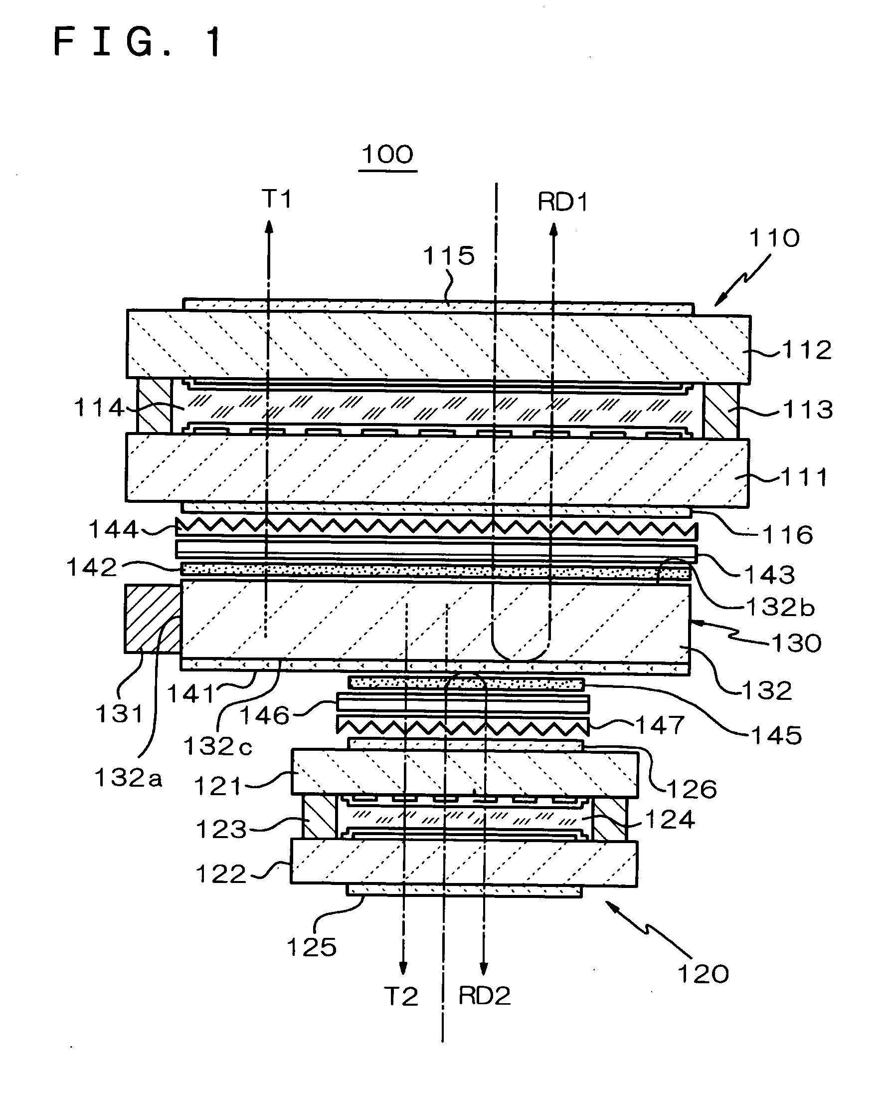
[0011] According to the present invention, with the common illumination unit constructed so as to illuminate both the first display unit and the second display unit with light, one of two illumination units can be eliminated, thereby achieving a thinner and lighter device. Also, with the transflector interposed between the second light-emitting surface of the light-guiding member of the illumination unit and the second display unit, since part of light emitted from the second light-emitting surface of the light-guiding member is transmitted through the transflector and is then directed towards the second display unit, while the second display unit is constructed so as to be illuminated with light, the remaining light emitted from the second light-emitting surface of the light-guiding member can be reflected at the transflector so as to be directed towards the first display unit. Accordingly, it is possible to place a priority on the illumination state of the first display unit, and hence the display quality of the first display unit can be improved.
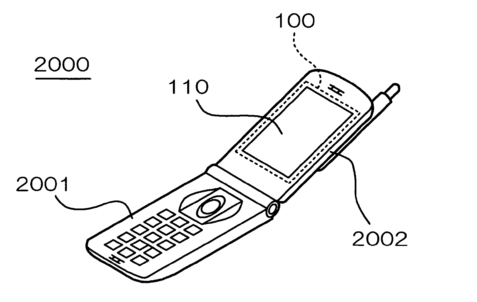
[0024] Next, an electronic apparatus according to the present invention preferably includes any one of the above-mentioned display devices and controllers for controlling the display device. Especially, as the above electronic apparatus, a portable electronic apparatus is effective from the viewpoint of easily achieving a thin casing thereof.

Problems solved by technology

Although a reflective liquid crystal display device having no such a backlight is available, its application is limited since its display is invisible in dark places and at night.
Although the liquid crystal display device equipped with a backlight has a drawback in thickness, with the recent advancements in higher definition and color display of a compact liquid crystal display device, most portable electronic apparatuses have them mounted thereon.
Unfortunately, the above-mentioned known cellular phone of a double-sided display type has problems in that, since a pair of liquid crystal display devices must be accommodated in its casing so as to lie back to back, it is hard to make the casing thinner, and, even when each of the liquid crystal display devices is made thin, the casing is thicker and heavier than a normal portable phone of a single-sided display type.
Whereas, in a cellular phone of a double-sided display type, since the display areas of the front and back liquid crystal display devices are generally different from each other, when a single backlight is shared by them as mentioned above, the luminance distribution of a large main panel is affected by an illumination action of the backlight applied on a small sub-panel disposed behind the main panel, thereby causing a risk that a shadow of the sub-panel is reflected in a display image of the main panel and thus its display quality deteriorates.
Meanwhile, the optical characteristics of the transflector mean characteristics such as a light reflectance, a light transmittance, a light absorptance, and a light-diffusing rate, possibly affecting the display features of the first display unit and the second display unit.

Method used


Image

  • Display device and electronic apparatus
  • Display device and electronic apparatus
  • Display device and electronic apparatus

Examples


first embodiment

[0033] First Embodiment

[0034] Referring first to FIG. 1, a liquid crystal display device 100 according to a first embodiment of the present invention will be described. The liquid crystal display device 100 includes a first display unit 110, a second display unit 120, and an illumination unit 130.

[0035] The first display unit 110 is a liquid crystal panel and is formed such that substrates 111 and 112 composed of glass or plastic are bonded to each other via a sealant 113 and have liquid crystal 114 interposed therebetween. The liquid crystal 114 is formed so as to receive predetermined electrical fields with electrodes formed on the inner surfaces of the substrates 111 and 112. The substrate 112 has a polarizer 115 disposed on the outer surface thereof, that is, on the front surface side or on the observing side of the first display unit, and the substrate 111 also has the polarizer 116 disposed on the outer surface thereof, that is, on the back surface side.

[0036] The second displ...

second embodiment

[0065] Second Embodiment

[0066] Referring next to FIG. 3, a display device according to a second embodiment of the present invention will be described. Since the display device according to the second embodiment basically has the same structure as that of the display device according to the first embodiment shown in FIG. 1 except for its transflector, illustrations and descriptions of the same parts in the second embodiment will be omitted.

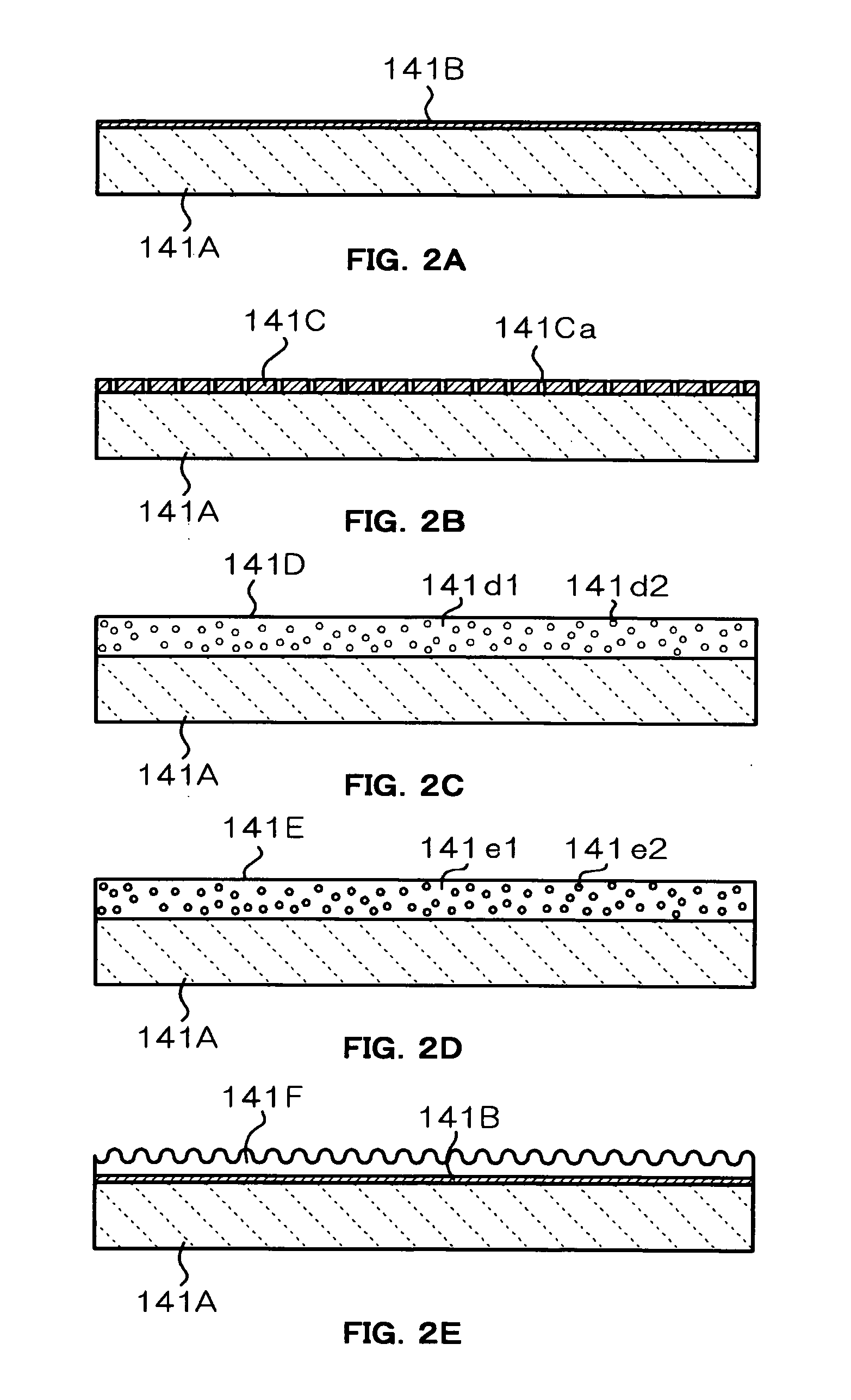
[0067] As shown in FIG. 3(a), a transflector 241 according to the present embodiment is interposed between the second light-emitting surface 132c of the light guiding plate 132 and the second display unit 120 so as to entirely cover a region AR1 two-dimensionally overlapping the display area of the first display unit 110. The transflector 241 has an overlapping portion AR2 which two-dimensionally overlaps the display area of the second display unit 120 and which serves as an aperture 241A, and in the region AR1, a portion AR3 other than the overlap...

third embodiment

[0070] Third Embodiment

[0071] Referring next to FIG. 4, a display device according to a third embodiment of the present invention will be described. Since the display device according to the present embodiment basically has the same structure as that of the display device according to the first embodiment shown in FIG. 1 except for its transflector, illustrations and descriptions of the same parts in the third embodiment will be omitted.

[0072] As shown in FIG. 4(a), in the region AR1, a transflector 341 is formed such that the overlapping portion AR2 is composed of a transflective material 341A having a predetermined reflectance and transmittance, for example, both in the range from 30 to 70%, and the portion AR3 other than the overlapping portion AR2 is composed of a reflective material 341B having a lower transmittance than that of the overlapping portion AR2 while having substantially the same reflectance as that of the overlapping portion AR2, for example, in the range from 30 t...


PUM

PropertyMeasurementUnit
transmittanceaaaaaaaaaa
thicknessaaaaaaaaaa
reflectanceaaaaaaaaaa

Abstract

A display device is provided which offers double-sided display and achieves a thin structure and also which prevents deterioration in display quality of each of front and back display units when an illumination unit such as a backlight is shared by these display units. The display device includes a first display unit having a display surface on the front surface thereof; a second display unit having a display surface on the rear surface thereof; and a common illumination unit interposed between the first display unit and the second display unit, for illuminating both the first display unit and the second display unit with light. The illumination unit includes a light-guiding member having a first light-emitting surface opposed to the first display unit and a second light-emitting surface opposed to the second display unit, and a transflector is interposed between the second light-emitting surface of the light-guiding member and the second display unit.

Description

[0001] 1. Field of the Invention[0002] The present invention relates to a display device and an electronic apparatus, and in particular, it relates to the structure of a display device suitably mounted on a portable electronic apparatus.[0003] 2. Related Art[0004] In general, an electro-optical device such as a liquid crystal display device or an electro-luminescent display device is used as a display device mounted on a portable electronic apparatus. In particular, a cellular phone has a compact liquid crystal display device mounted in a small casing thereof. In recent years, a cellular phone of a double-sided display type, having compact liquid crystal display devices mounted on the front and back of a thin displaying portion thereof, is commercially available on the market. Such a cellular phone has a pair of liquid crystal display devices accommodated in the displaying portion of the casing thereof so as to lie back to back and placed so as to be visible from both the front and ...

Claims


Application Information

Patent Timeline
Patent Type & Authority Applications(United States)
IPC IPC(8): G02F1/1347F21V8/00F21Y101/02F21Y103/00G02F1/1335G02F1/13357H04M1/02H04M1/22
CPCG02F1/133615G02F2001/133342H04M2250/16H04M1/22H04M1/0214G02F1/133342G02F1/1335
Inventor ONISHI, YASUNORIKAWAKAMI, HISANORIMASAMOTO, TAKETOSHI
Owner TCL CHINA STAR OPTOELECTRONICS TECH CO LTD
Learn More