
Method and cooling device for the subracks in a chamber furnance

Inactive Publication Date: 2004-07-15
ALUMINUM PECHINEY
View PDF10 Cites 0 Cited by
  • Summary
  • Abstract
  • Description
  • Claims
  • Application Information

AI Technical Summary

Problems solved by technology

However, the pit cooling times after the removal of the carbonaceous blocks, which are very long, limit the productivity of the furnaces when actions are required on the furnace, particularly the replacement of partitions,

Method used


Image

  • Method and cooling device for the subracks in a chamber furnance
  • Method and cooling device for the subracks in a chamber furnance
  • Method and cooling device for the subracks in a chamber furnance

Examples


Example

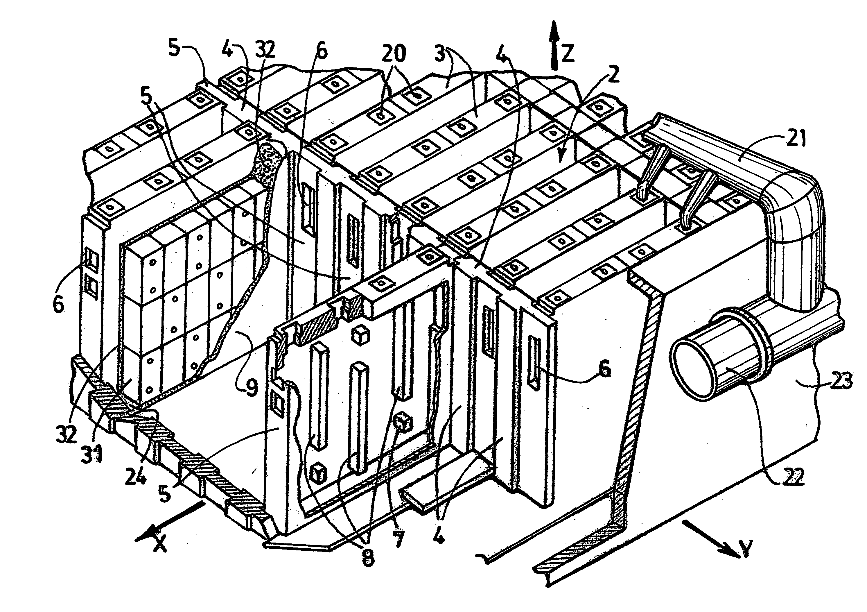
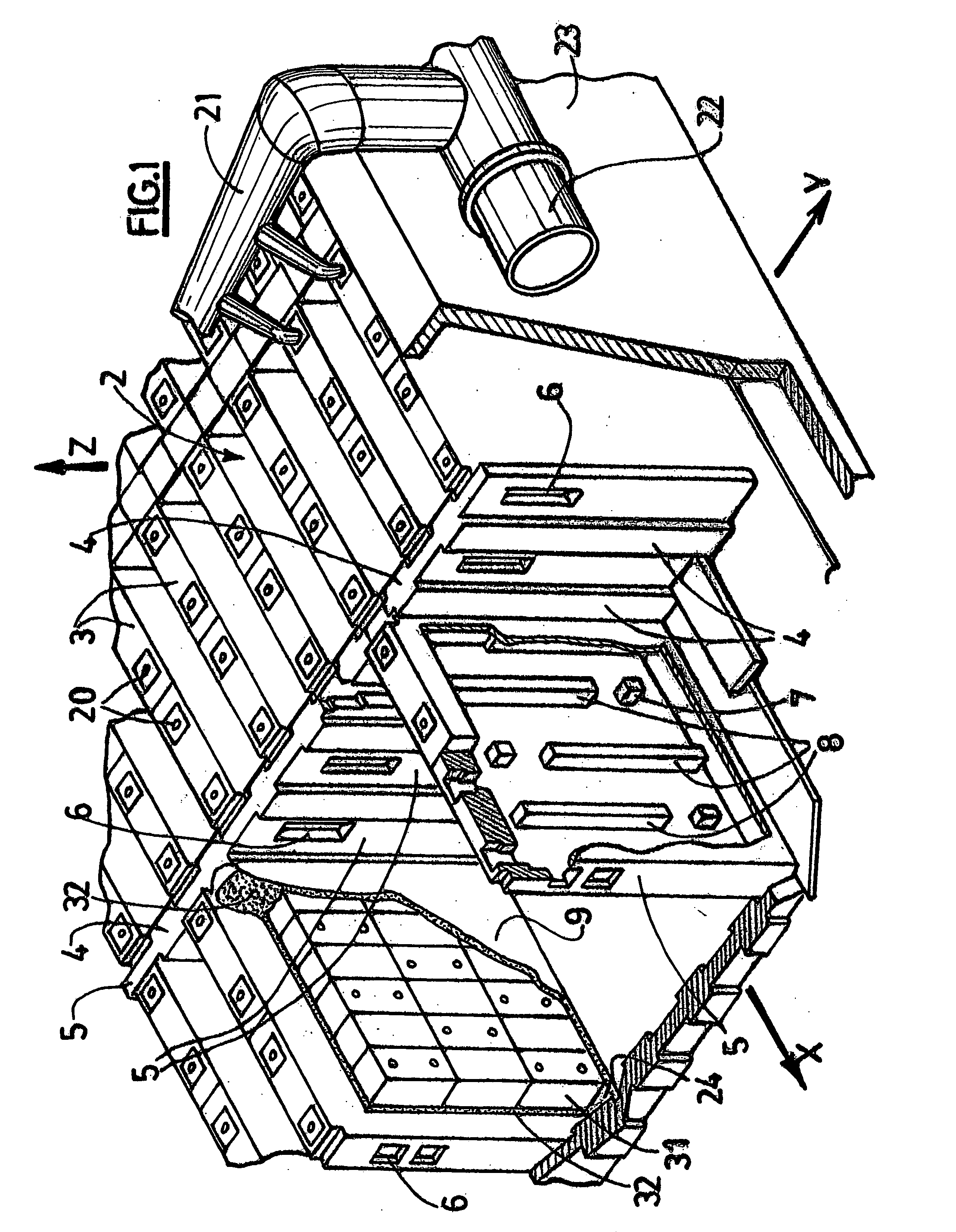
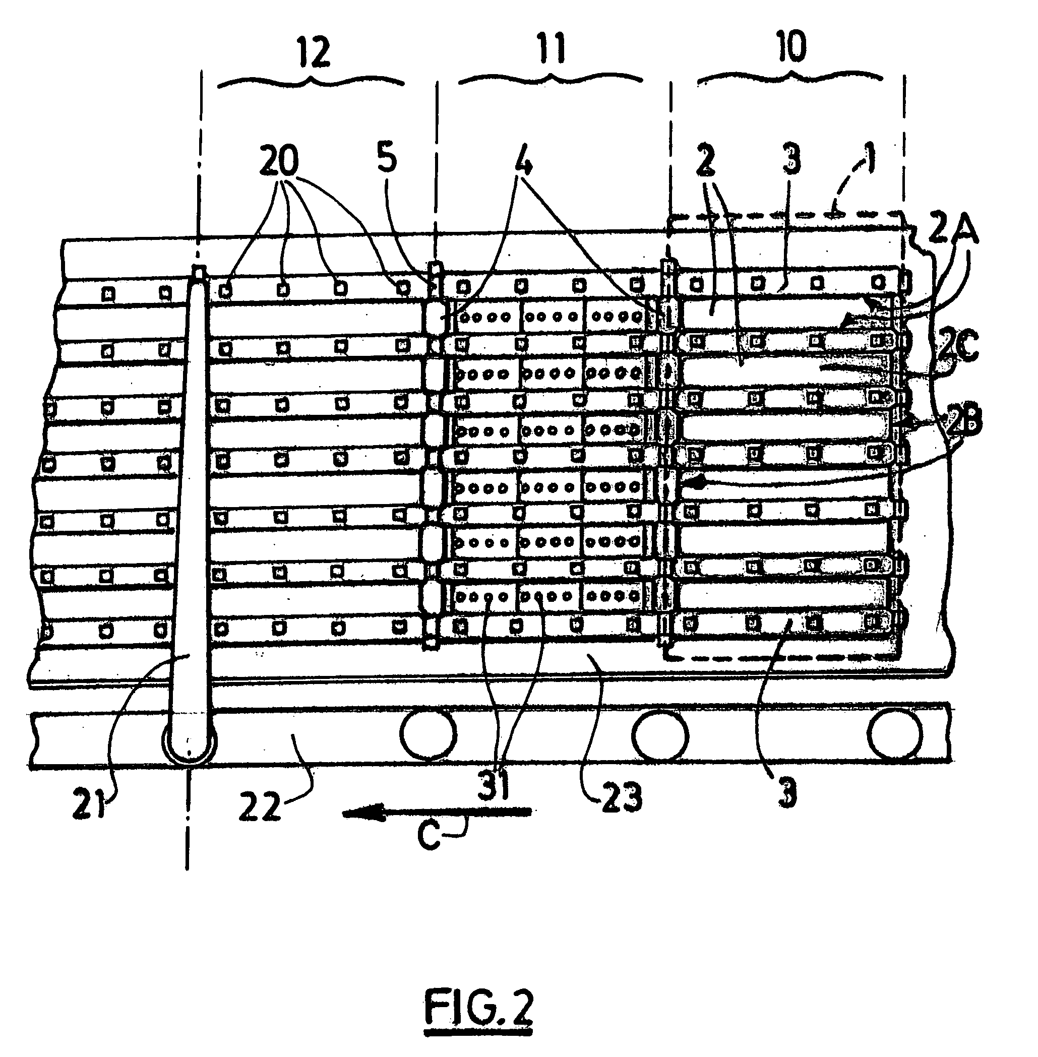
[0008] The invention relates to a ring furnace pit cooling method characterised in that it comprises the production of a flux F of cooling fluid inside the pit and in that at least a part Fr of said flux F flows in a roughly vertical manner along determined surfaces of the walls of the pit.

[0009] The invention also relates to a ring furnace pit cooling device characterised in that it comprises:

[0010] at least one first means capable of producing a flux F of cooling fluid inside the pit, such as a ventilation means;

[0011] at least one second means capable of inducing a roughly vertical flow of at least a part Fr of said flux F along determined surfaces of the walls of the pit, such as a confinement means.

[0012] The invention also relates to a ring furnace pit cooling method using the device according to the invention.

[0013] The applicant observed that the roughly vertical flow of the cooling fluid flux in the vicinity of the pit walls made it possible to accelerate the cooling rate o...


PUM


Abstract

The invention relates to a ring furnace pit (2) cooling method, comprising the production of a flux F of cooling fluid inside the pit (2) and the flow of at least a part Fr of said flux F in a roughly vertical manner along determined surfaces of the walls (2A, 2B) of the pit (2). The invention also relates to a device capable of implementing the method. The invention makes it possible to accelerate the cooling rate of ring furnace pits considerably.

Description

[0001] The invention relates to the field of so-called "ring furnaces" for firing carbonaceous blocks, and particularly open type chamber furnaces. The invention relates more specifically to a method and a device to cool the pits of such furnaces before servicing and maintenance operations.STATE OF THE ART[0002] Open type ring furnaces are well known themselves and are particularly disclosed in the French patent applications FR 2 600 152 (corresponding to the American patent U.S. Pat. No. 4,859,175) and FR 2 535 834 (corresponding to the British application GB 2 129 918).[0003] A ring furnace comprises a succession of aligned chambers, each chamber comprising a plurality of elongated pits separated by hollow heating partitions.[0004] A carbonaceous block firing cycle, for a given chamber, typically comprises the loading of the pits of said chamber with unprocessed carbonaceous blocks, heating of said chamber to the carbonaceous block firing temperature (typically from 1100 to 1200.d...

Claims


Application Information

Patent Timeline
IPC IPC(8): F27B13/02F27D9/00
CPCF27B13/02
Inventor DREYER, CHRISTIANBACKHOUSE, NIGEL
Owner ALUMINUM PECHINEY
Learn More