
Moveable heat exchanger

a heat exchanger and moving technology, applied in the field of moving heat exchangers, can solve the problems of high nitrogen concentration in the superficial layer, insufficient cooling rate of components, and inability to easily repeat conventional gas nitriding to achieve consistent, etc., and achieve the effect of cooling rate of workpieces

Inactive Publication Date: 2003-09-30
NITREX METAL
View PDF8 Cites 3 Cited by
  • Summary
  • Abstract
  • Description
  • Claims
  • Application Information

AI Technical Summary

Benefits of technology

In accordance with the present invention there is provided a method for cooling a workpiece within a high-temperature chamber comprising the steps of: heating the workpiece; and, moving a moveable heat exchanger into the high-temperature chamber, such that a cooling rate of the workpiece is achieved that is relatively faster than a cooling rate obtained absent the moveable heat exchanger.
According to a further aspect of the invention there is provided an apparatus for cooling a workpiece within a high-temperature chamber comprising: a heat exchanger moveable between a first position in which the heat exchanger is thermally isolated from a gas atmosphere contained within the high-temperature chamber and a second position in which the heat exchanger is in thermal communication with the gas atmosphere; an actuator operatively coupled to the heat exchanger for moving selectively the heat exchanger between the first position and second position through a port of the high-temperature chamber; and, a seal disposed between opposing surfaces of the heat exchanger and the port for substantially containing the gas atmosphere within the high temperature chamber.
According to another aspect of the invention there is provided a heat treatment system comprising: a moveable heat exchanger; a high-temperature chamber having a port through a wall surface thereof for sealingly engaging an opposing surface of the heat exchanger and for permitting at least a portion of the heat exchanger to be removeably inserted within the high-temperature chamber, and having at least an orifice in communication with an atmosphere control system for providing a gas atmosphere with a predetermined composition; an actuator operatively coupled to the heat exchanger for relatively moving the heat exchanger to the high-temperature chamber to selectively insert the at least a portion of the heat exchanger through the port; a process controller in electrical communication with the actuator for providing to the actuator a first control signal for controlling the movement of the heat exchanger, wherein, in use, the heat exchanger is in thermal communication with the gas atmosphere when inserted in the high-temperature chamber and thermally isolated from the gas atmosphere when removed from the high-temperature chamber.

Problems solved by technology

Such high nitrogen concentrations in the superficial layer are undesirable as they are the cause of porosity, brittleness and spalling.
In addition, conventional gas nitriding cannot easily be repeated to achieve consistent results.
Unfortunately, the maximum cooling rate that is attainable using a prior art furnace often is insufficient to rapidly cool the components while simultaneously maintaining a constant nitriding potential of the furnace atmosphere.
As a result, the case hardened components may not develop the expected properties and may even be at risk of failing prematurely.
More specifically, the toxic atmosphere of partially dissociated ammonia cannot easily be vented to outside of the furnace without first being neutralized using special equipment.
Venting of the atmosphere creates an additional problem in that the cooling gas supplied to replace the vented atmosphere must have an identical composition, thus increasing the operating costs associated with acquisition and disposal of toxic chemical substances.
Unfortunately, such an apparatus is poorly suited for batch-processing operations, for example using a pit furnace to case harden large loads of metal components.
It is a disadvantage of the prior art systems that nitrided components are transferred to a second other chamber subsequent to high-temperature treatment for cooling under a separate atmosphere.
Often, undesirable nitride precipitates develop at component surfaces that are cooled under an improperly controlled atmosphere.

Method used


Image

  • Moveable heat exchanger
  • Moveable heat exchanger
  • Moveable heat exchanger

Examples


first embodiment

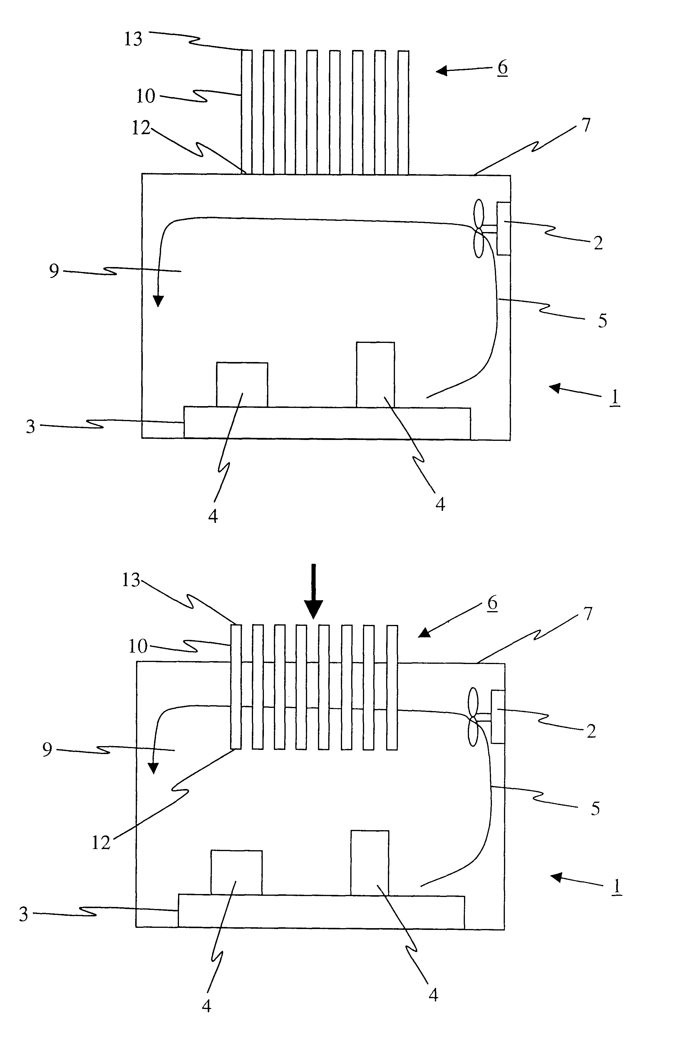
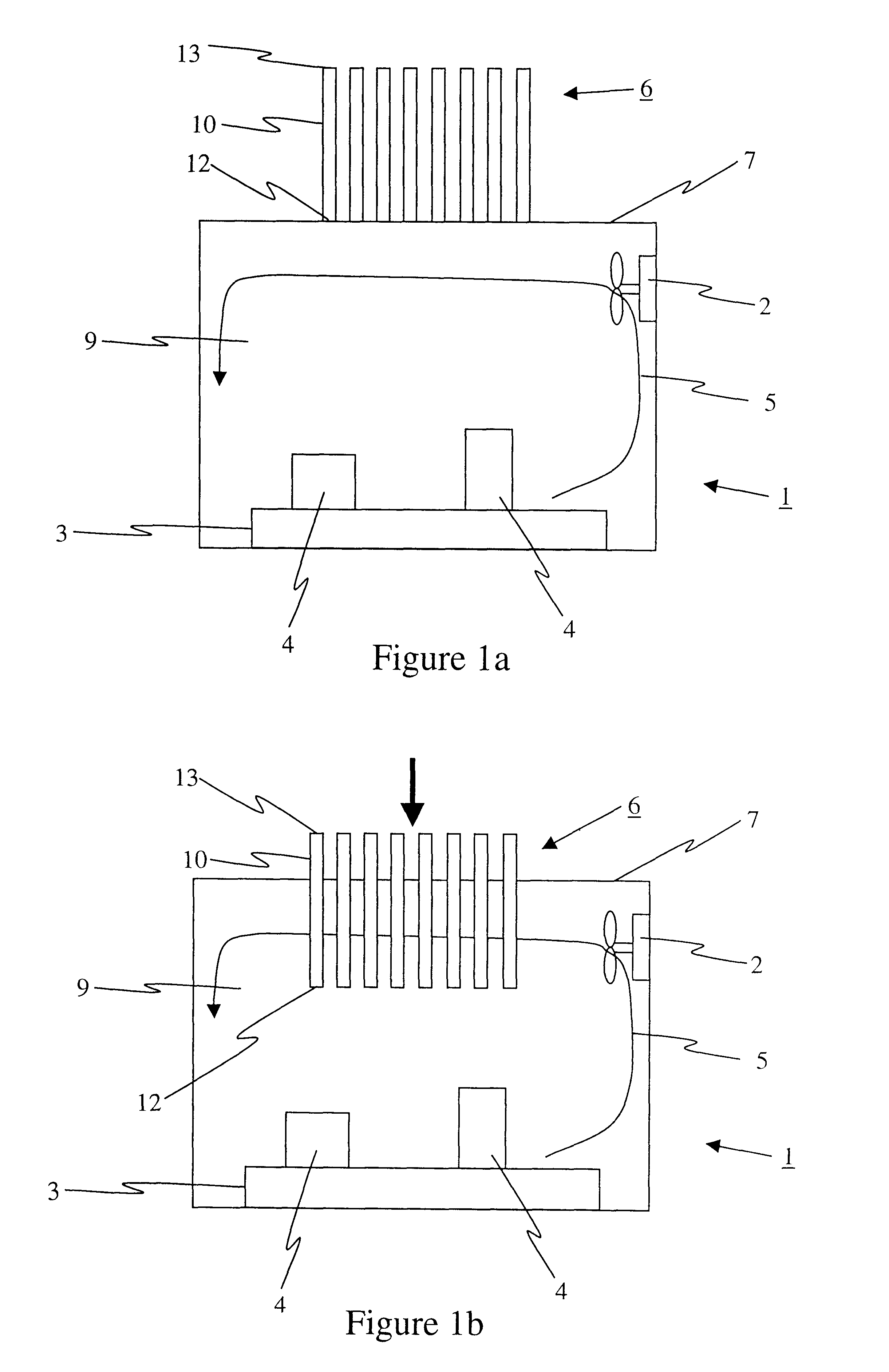
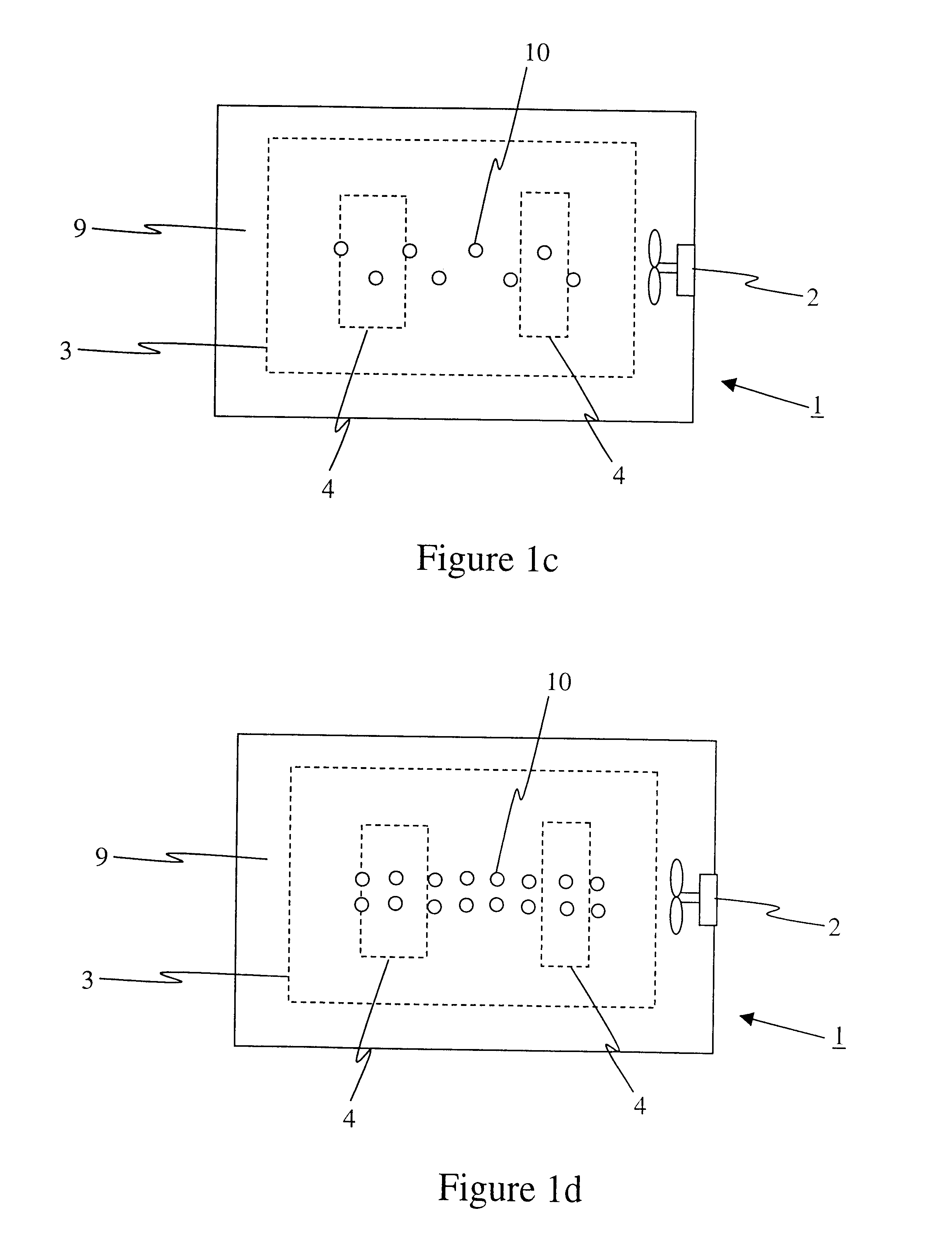
Referring to FIGS. 1a and 3a, simplified block diagrams of a moveable heat exchanger 6 in a first position are shown according to the instant invention. The moveable heat exchanger 6 comprises at least a cooling rod 10 disposed adjacent to a wall surface 7 of a high temperature chamber, such as for instance a nitriding furnace 1. Most preferably, the moveable heat exchanger 6 comprises a plurality of rods. Each rod 10 is disposed relative to the surface 7 such that the rod 10 engages at an insulated first end 12 thereof a matching port (not shown) of the surface 7. The insulated first end 12, which is shown most clearly in FIG. 3a, reduces heat transfer from the cavity 9 to the rod 10 during the high-temperature portion of the nitriding process. An actuator (not shown) is provided for relatively moving the rods 10 with respect to the furnace 1 to removeably insert the rods 10 at least partially into the cavity 9. The actuator is selected from a group including: a hydraulic actuator,...

second embodiment

Referring now to FIGS. 2a and 4a, simplified block diagrams of a moveable unified heat exchanger 20 in a first position are shown according to the instant invention. The moveable unified heat exchanger 20 comprises a housing including a first insulated surface 21 and a second insulated surface 22, the housing for supporting at least a heat exchange surface whilst allowing atmospheric circulation therethrough. In the first position the moveable unified heat exchanger 20 is disposed adjacent to a wall surface 7 of a high temperature chamber, such as for instance a nitriding furnace 1. Most preferably, a surface of the moveable unified heat exchanger 20, such as for instance the first insulated surface 21, is substantially continuous with the surface 7 of the furnace 1. The first insulated surface 21 reduces heat transfer from the cavity 9 to the moveable unified heat exchanger 20 during the high-temperature portion of the nitriding process when the heat exchanger 20 is in the first po...


PUM

PropertyMeasurementUnit
temperatureaaaaaaaaaa
surface areaaaaaaaaaaa
seizing resistanceaaaaaaaaaa

Abstract

Disclosed is a moveable heat exchanger for use with a high temperature chamber, such as for instance a nitriding furnace. The heat exchanger is between a first position external to the furnace, and a second position in which the heat exchanger projects substantially into the furnace through an opening in a wall surface of the furnace. In use, the heat exchanger is in the first position during a high temperature portion of a process and is in the second position during a cooling portion subsequent to the high temperature portion of the process. The heat exchanger sealingly engages the wall surface about its periphery to prevent the exchange of atmospheric components in either direction between the interior of the furnace and the outside.

Description

FIELD OF THE INVENTIONThis invention relates generally to heat exchangers for rapidly cooling the contents of a high-temperature chamber. In particular, this invention relates to a heat exchanger movable between a first position external to the chamber during a high-temperature step of a process and a second position internal to the chamber during a cooling step of the process.BACKGROUND OF THE INVENTIONNitriding is a process of enriching with nitrogen the surface layer of steel, resulting in the formation of a hardened surface on machine components with improved fatigue, wear and / or seizing resistance. In conventional gas nitriding, carried out in partially dissociated ammonia gas at 500-600.degree. C., the superficial nitrogen concentration cannot be controlled. The combined nitrogen and carbon concentration at the surface reaches 11.3%, bringing about the formation of a single phase zone consisting mainly of carbonitrides. Such high nitrogen concentrations in the superficial laye...

Claims


Application Information

Patent Timeline
Patent Type & Authority Patents(United States)
IPC IPC(8): C21D1/84C21D1/74C21D1/767C23C8/24F27D9/00F25D17/02F25D17/00F27B17/00F27D19/00
CPCC21D1/767C21D1/84C23C8/24F27D9/00F25D17/02F27B17/0083F27D19/00Y10S165/912
Inventor KORWIN, MICHEL J.SZYMBORSKI, JANUSZ
Owner NITREX METAL
Learn More