
Pearlitic steel rail having excellent wear resistance and method of producing the same

a technology wear resistance, which is applied in the field of pearlitic steel rail, can solve the problems of reducing the affecting the service life of the rail, and affecting the service life of the rail, and achieves the effect of securing wear resistance and low hardness

Inactive Publication Date: 2009-12-08
NIPPON STEEL CORP
View PDF43 Cites 5 Cited by
  • Summary
  • Abstract
  • Description
  • Claims
  • Application Information

AI Technical Summary

Benefits of technology

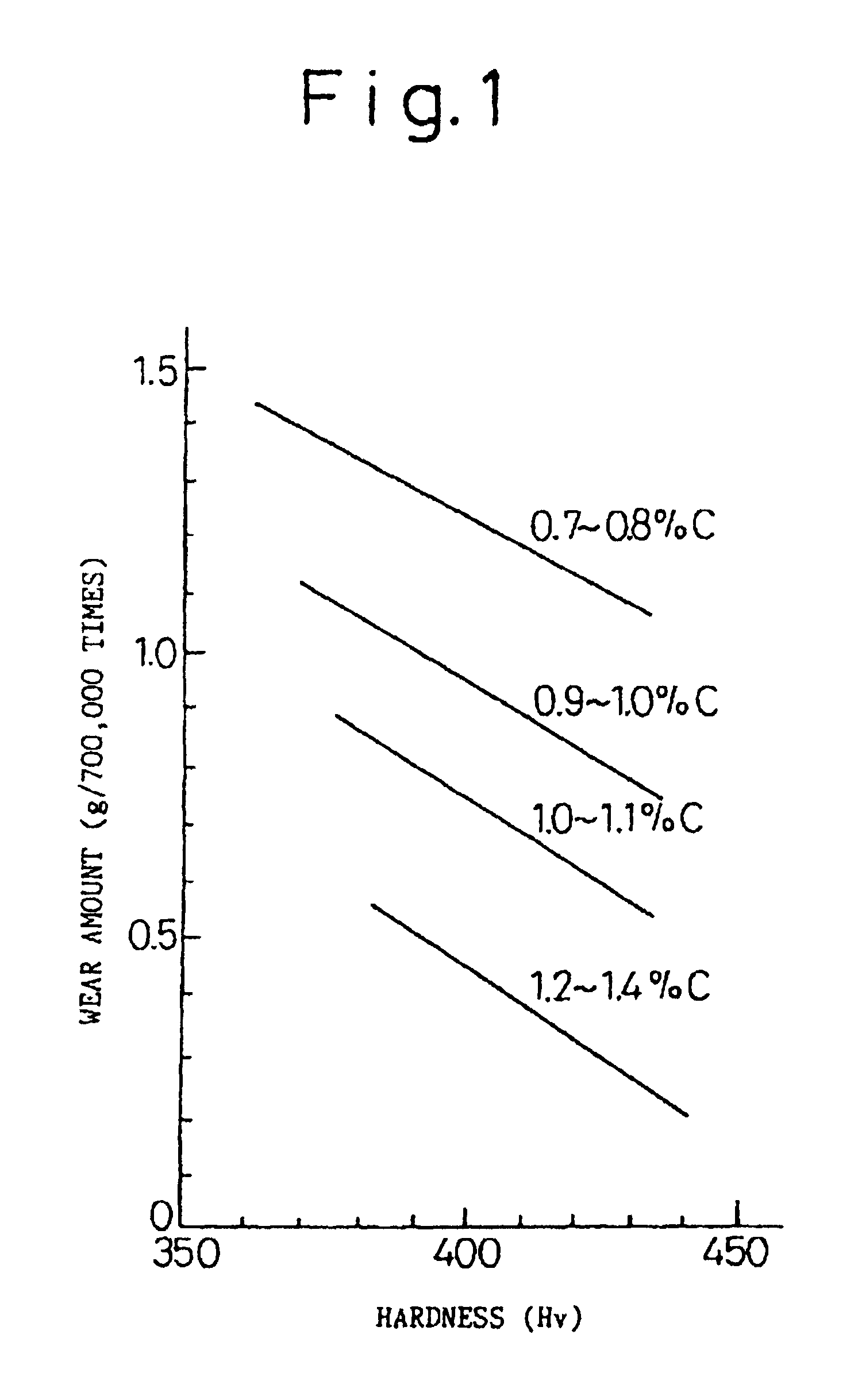
The present invention relates to a pearlitic steel rail with improved wear resistance and damage resistance. The technical effects of the invention include increasing the hardness of the pearlite structure by increasing the carbon content and the ratio of hard cementite layer, and increasing the cementite density immediately below the rolling surface. The invention also addresses the problem of pro-eutectic cementite formation and promotes the formation of a good wear resistance by reducing the contact surface pressure and the wear of the head top portion. Additionally, the invention addresses the problem of resistance flash butt welding in rail welding and provides a solution to prevent damage to the rails and road bed.

Problems solved by technology

More concretely, wear drastically increases in the rails laid down in a curved zone of a heavy load railway and produces a problem from the aspect of longer service life of the rails.
In the case where the rails are sharply curved, the wear resistance cannot be secured even when the rails developed as described above are used, and the drop of rail life due to the wear has become a serious problem.
The contact state between the wheel and the rail is complicated.
On the head top portion of the inner track rail of the curved zone, on the other hand, the rail receives great slipping contact having large contact surface pressure from the wheel.
Therefore, fatigue damage builds up on the head top surface before it is worn out.
Therefore, if fitting of the rail to the wheel is not quick at the initial wear state immediately after the laying of the rail, a local and excessive contact surface pressure consecutively acts on the rail and surface damage due to fatigue is likely to occur.
In addition, even after fitting is established between the rail and the wheel, a large contact surface pressure always acts on the head top portion and consequently, surface damage similar to so-called “head check”, which generally occurs at the gage corner portion, develops with plastic deformation because the wear is less.
Because the cutting work requires a long time and is expensive, the following rail has been developed.
However, higher axial load of cargos (increase of railway loading) has been vigorously promoted in recent years so as to attain higher efficiency of railway transportation, and even when the rails developed as described above are used, sufficient wear resistance cannot be secured at the gage corner portions of the outer track rail even though they can prevent the surface damage by the periodically grinding of the head top portion in the inner track rail at the sharply curved zone, and the drop of rail life due to wear has been a serious problem.

Method used


Image

  • Pearlitic steel rail having excellent wear resistance and method of producing the same
  • Pearlitic steel rail having excellent wear resistance and method of producing the same
  • Pearlitic steel rail having excellent wear resistance and method of producing the same

Examples


example 1

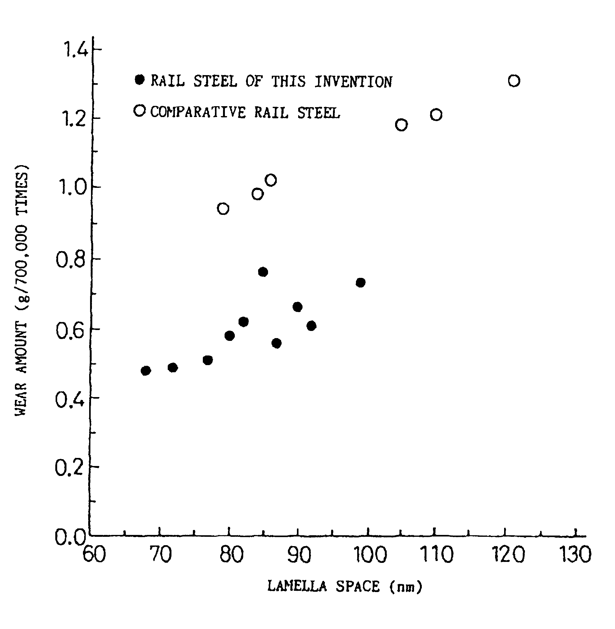
[0132]Table 1 tabulates the chemical components of the rail steel having the pearlite structure of this Example 1 of the present invention and the chemical components of a Comparative rail steel. Table 2 tabulates the lamella space λ (λ=ferrite thickness t1+cementite thickness t2), the ratio Rc (Rc=t2 / t1) and the result of measurement of the wear quantity after repetition of 500,000 times under a dry condition by a Nishihara type wear test of each of these steels.

[0133]Further, FIGS. 3 and 4 show the relation between the lamella space (λ) and the ratio of the cementite thickness to the ferrite thickness and the relation between the lamella space (λ) and the wear quantity of the Comparative rail steel and the present rail steel. FIG. 5 shows a 10,000× micrograph of the present rail steel (No. 8). FIG. 5 is obtained by etching the present rail steel by a 5% nital solution and observing it through a scanning electron micrograph. A white portion in the drawing represents the cementite l...

example 2

[0149]Table 3 shows the chemical components of the Present rail steels and the accelerated cooling condition, and Table 4 shows the chemical components of the Comparative rail steels and the accelerated cooling condition. Further, Tables 3 and 4 represent also the hardness after accelerated cooling and the measurement result of the wear amount after repetition of 700,000 times under the compulsive cooling condition by compressed air in the Nishihara type wear test shown in FIG. 7.

[0150]FIG. 8 graphically compares the wear test results between the Present rail steels and the Comparative rail steels shown in Tables 1 and 4 in terms of the relation between the hardness and the wear amount.

[0151]By the way, the rail construction is as follows.

Present rails (16 rails) Nos. 17 to 32

[0152]Heat-treated rails having the components within the range described above, and exhibiting the pearlite structure within the range of depth of at least 20 mm from the surfaces of the gage corner portion an...

example 3

[0156]Table 5 tabulates the chemical components, the accelerated cooling rate at the time of heat-treatment of the rails and the pearlite structure fractions at the stop of accelerated cooling of each of the present rail steels and Comparative rail steels. Further, Table 6 tabulates the hardness (Hv) of the head surface after heat-treatment of the rails and the wear amount after the Nishihara type wear test of each of the present rail steels and the Comparative rail steels. The wear test results of the rail head materials by the Nishihara type wear tester shown in FIG. 7 are shown.

[0157]By the way, the wear testing condition are as follows.[0158]Testing machine: Nishihara type wear tester[0159]Shape of testpiece: disc-like testpiece (outer diameter: 30 mm, thickness: 8 mm)[0160]Test load: 686N[0161]Slippage ratio: 20%[0162]Wheel material: pearlite steel (Hv 390)[0163]Atmosphere: in air (compulsive cooling by compressed air)[0164]Number of times of repetition: 700,000 times

[0165]

TABL...


PUM

PropertyMeasurementUnit
thicknessaaaaaaaaaa
temperatureaaaaaaaaaa

Abstract

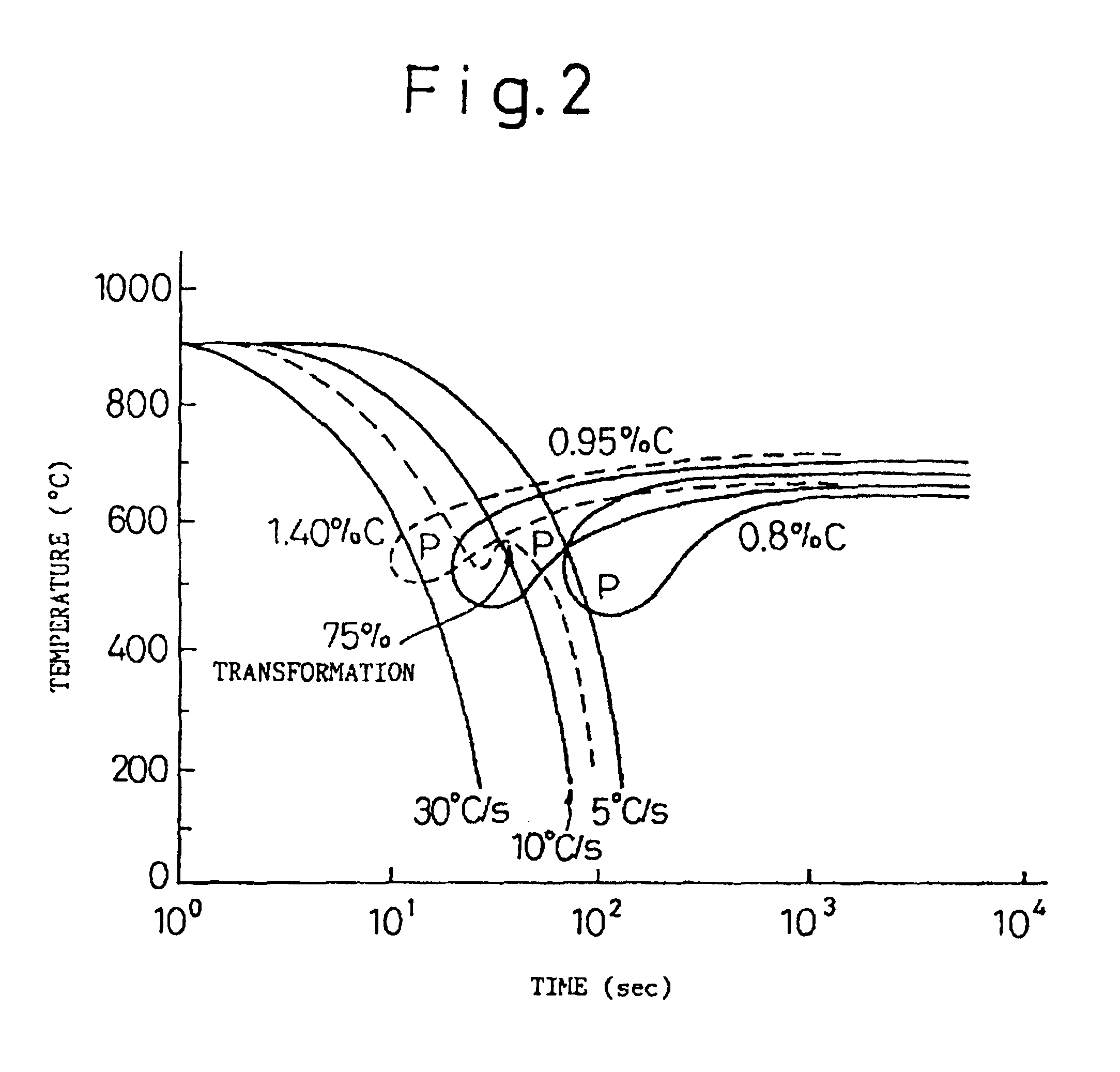
This invention is directed to improve a wear resistance and a damage resistance required for a rail of a sharply curved zone of a heavy load railway, comprising more than 0.85 to 1.20% of C, 0.10 to 1.00% of Si, 0.40 to 1.50% of Mn and if necessary, at least one member selected from the group consisting of Cr, Mo, V, Nb, Co and B, and retaining high temperature of hot rolling or a steel rail heated to a high temperature for the purpose of heat-treatment, the present invention provides a pearlitic steel rail having a good wear resistance and a good damage resistance, and a method of producing the same, wherein a head portion of the steel rail is acceleratedly cooled at a rate of 1° to 10° C. / sec from an austenite zone temperature to a cooling stop temperature of 700° to 500° C. so that the hardness of the head portion is at least Hv 320 within the range of a 20 mm depth.

Description

CROSS-REFERENCE TO RELATED APPLICATION(S)[0001]The present application is a continuation of U.S. patent application Ser. No. 10 / 974,048 filed Oct. 26, 2004, which is a reissue application of U.S. Pat. No. 5,762,723 which issued on Jun. 9, 1998. The entire disclosures of the application and U.S. Patent referenced above are incorporated herein by reference.TECHNICAL FIELD[0002]This invention relates to a pearlitic steel rail which improves the wear resistance and breakage resistance that are required for rails at curved zones of heavy load railways, and drastically improves the service life of the rails, and a method of producing such rails.BACKGROUND ART[0003]Attempts have been made to improve a train speed and loading as one of the means for accomplishing higher efficiency of railway transportation. Such as improvement in efficiency of railway transportation means severe use of the rails, and a further improvement in the rail materials has become necessary. More concretely, wear dra...

Claims


Application Information

Patent Timeline
Patent Type & Authority Patents(United States)
IPC IPC(8): C21D1/84C21D9/04
CPCC21D1/84C21D9/04C21D2211/009C22C38/32C21D8/02
Inventor UEDA, MASAHARUKAGEYAMA, HIDEAKIUCHINO, KOUICHIBABAZONO, KOJIKUTARAGI, KEN
Owner NIPPON STEEL CORP
Learn More