

Monitor for injection molding machine
a technology for monitoring machines and injection molding machines, which is applied in the direction of manufacturing tools, simultaneous indication of multiple variables, instruments, etc., can solve the problems of difficult to distinguish the changes in waveform patterns of molding cycles from each other, difficult to discriminate variations, changes, trends in waveform patterns from each other, etc., and it is impossible to grasp the variation and how of variables
- Summary
- Abstract
- Description
- Claims
- Application Information
AI Technical Summary
Benefits of technology
Problems solved by technology
Method used
Image

Examples
first embodiment
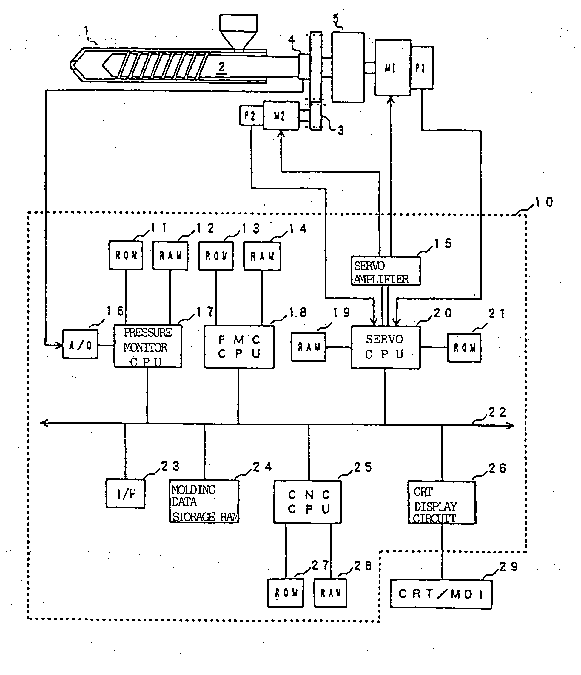
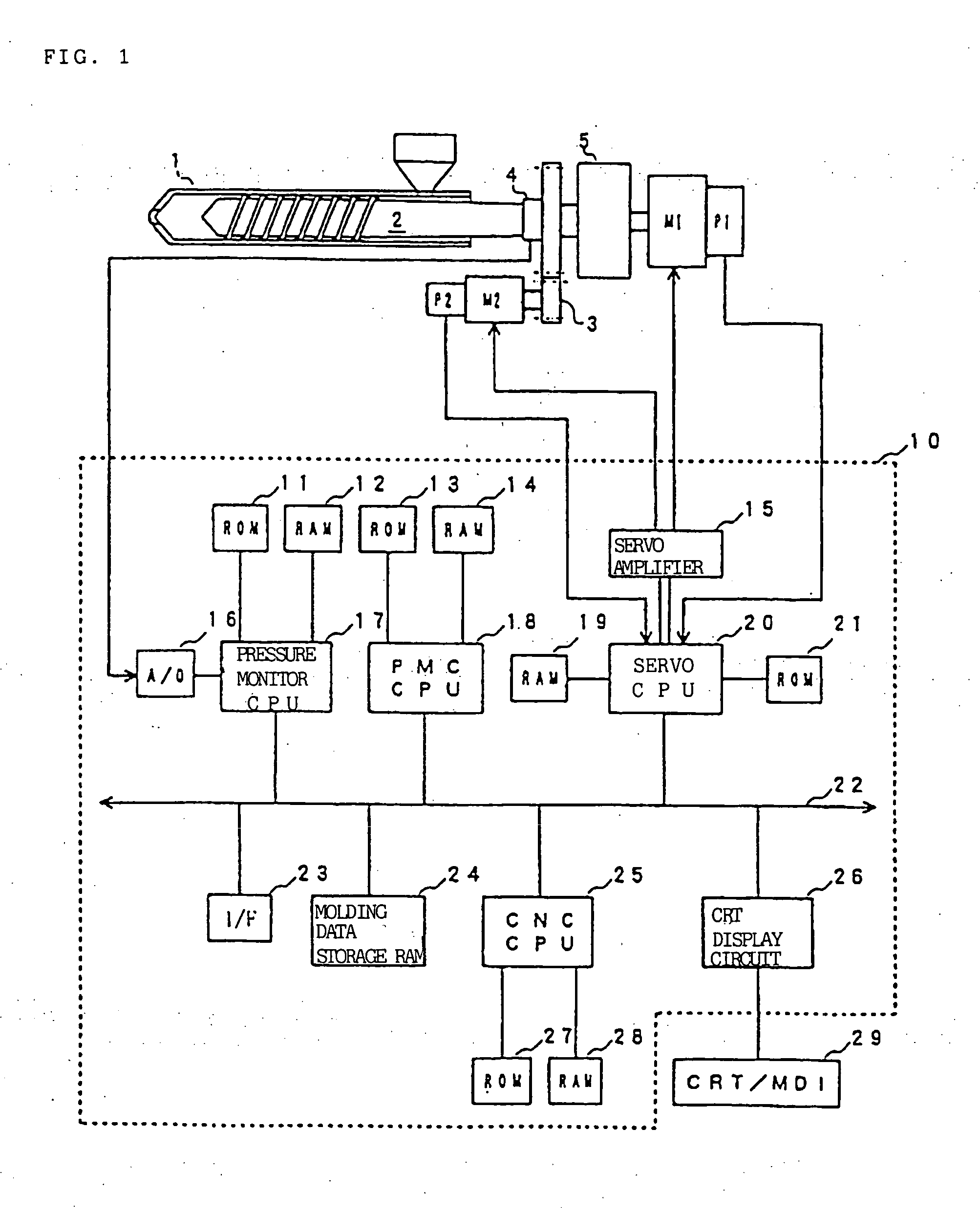
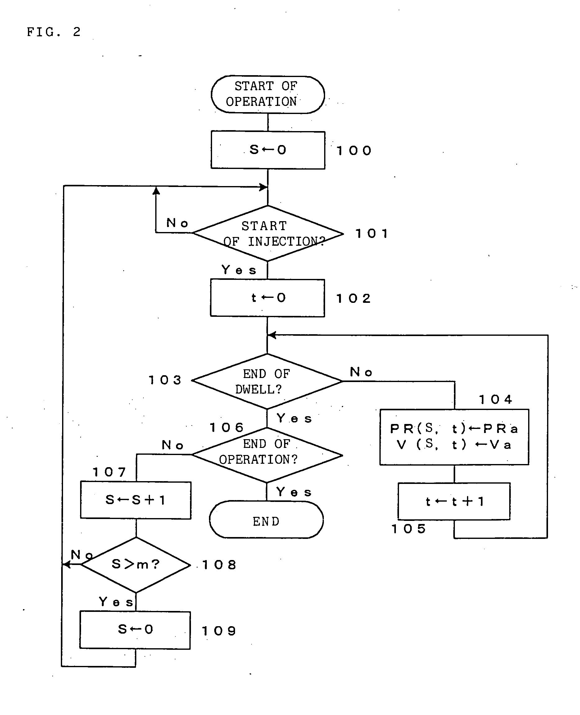
[0047] FIG. 2 is a flow chart of monitor data obtaining processing performed by the pressure monitor CPU 17 in the In this embodiment, an injection pressure PR and an injection velocity V are detected as monitor data at every predetermined sampling cycle.
[0048] If operation starts, a shot counter S for counting the number of molding cycles (number of shots (injections)) at "0" (step 100). If the injection starts (step 101), a sampling counter t for counting the number of sampling is set at "0" (step 102) and whether dwell process has finished or not is judged (step 103). If dwell process has not been finished, a current injection pressure PRa detected from a load cell and a current injection velocity Va detected from the position / velocity detector are respectively stored in a table provided in the RAM 12 as PR(S, t) and V(S, t), respectively, in association with values of the shot counter S and the sampling counter t (step 104).
[0049] The table provided in the RAM 12 is a table for...
third embodiment
[0070] Then, in the third embodiment, the injection pressure PR, the injection velocity V and the time T at every predetermined sampling cycle are stored at every shot in the table as shown in FIG. 10.
[0071] Although the monitor data displaying processing in the third embodiment is mostly similar to the displaying processing in the first embodiment shown in FIG. 4, the processing at step 205 is different and the other processings are the same. In the third embodiment, as shown in FIG. 11, a first axis represents the sampling time, a second axis represents the injection pressure PR and the injection velocity V, a third axis represents a dwell end time T in each the molding cycle, and patterns of the injection pressure PR and the injection velocity V with respect to time are drawn at a position on the third axis corresponding to the dwell end time T stored in the table.
[0072] In a case of the third embodiment, in the processing at step 205, a position corresponding to a value obtained...
fourth embodiment
[0074] In a case of the fourth embodiment, the injection pressure PR, the injection velocity V, the screw position PO, and the dwell end time T at every sampling time are stored at every molding cycle (every shot) in the table provided to the RAM 12 as shown in FIG. 13.
[0075] In the monitor data displaying processing in the fourth embodiment, the first axis represents the screw position, the second axis represents the injection pressure PR and the injection velocity V, the third axis represents the dwell end time T in each molding cycle as shown in FIG. 14, and the injection pressure PR and the injection velocity V are plotted at a position on the third axis corresponding to the dwell end time T stored in the table, in association with the screw position PO, so that the patterns of the injection pressure PR and the injection velocity V with respect to the screw position PO are drawn.
[0076] Although the variables (such as injection pressure, injection velocity, screw position) are de...
PUM
| Property | Measurement | Unit |
|---|---|---|
| time | aaaaa | aaaaa |
| temperatures | aaaaa | aaaaa |
| pressure | aaaaa | aaaaa |
Abstract
Description
Claims
Application Information