Apparatus and method for injecting a liquid dye into a polymer melt

a technology of liquid dye and polymer melt, which is applied in the direction of machines/engines, positive displacement liquid engines, transportation and packaging, etc., can solve the problems of metering pump volumetric loss, metering pump bridge, negative effect, etc., and achieve safe and accurate addition of liquid dye, small volumetric loss, and the effect of easy operation

Inactive Publication Date: 2007-10-09
SAURER GMBH & CO KG
View PDF15 Cites 34 Cited by
  • Summary
  • Abstract
  • Description
  • Claims
  • Application Information

AI Technical Summary

Benefits of technology

[0008]The special advantage of the invention lies in that a liquid dye can be added to the polymer melt in any position within the melt carrying components of a spin unit or another melt carrying unit by metering the quantity with the greatest possible accuracy. In particular, the invention makes it easily possible to add a dye safely and accurately in places, in which the polymer melt advances through a melt carrying component under a high overpressure. To this end, the metering inlet of the metering pump is connected to a feed outlet of the feed pump, which in turn connects via a feed inlet to the tank. In this respect, an advantage of the invention lies in that there is a separation between the functions of “feeding the dye” and “metering the dye.” In this process, the feed pump removes the liquid dye from the tank and supplies it under pressure to the metering pump. Corresponding pressure adjustments at the metering inlet of the metering pump permit setting minimal pressure differences, so that very small volumetric losses occur when metering the liquid dye by means of the metering pump.
[0009]To adapt the discharge of the feed pump as much as possible to the metered quantity of the metering pump, an advantageous further development of the invention provides for respectively associating a controllable pump drive to the metering pump and to the feed pump. The pump drives are separately activated via a control unit.
[0010]In this connection, the adjustment of a feed pressure at the metering inlet of the metering pump is advantageously monitored and adjusted by arranging a pressure sensor between the feed outlet of the feed pump and the metering inlet of the metering pump. The pressure sensor connects via a signaling line to the control unit, so that it is possible to perform within the control unit a comparison between actual and desired values, and to make in the case of a deviation a corresponding correction directly in the control of the feed pump.
[0011]To keep the number of components required for adjustment and control as small as possible, it is advantageous to operate the metering pump and the feed pump by a common pump drive. To ensure that a pressure is able to build up between the feed pump and the metering pump, the feed pump is designed for delivering a greater volume than the metering pump. This makes it possible to obtain a surplus in the delivery of the liquid dye also at the same drive speed of the two pumps.
[0012]Since in the case of an excessive delivery it is necessary to keep the feed pressure at the level of a desired value, an advantageous further development of the invention provides for connecting the feed outlet of the feed pump via a feed line to the metering inlet of the metering pump. In this case, the feed line is coupled via a pressure control valve with a bypass line. The pressure control valve makes it possible to adjust a desired value of the feed pressure within the feed line. If the desired value of the pressure is exceeded, a portion of the liquid dye will be discharged from the feed line via the pressure control valve and the bypass line.
[0013]Advantageously, the bypass line is coupled directly with the tank or with the feed inlet of the feed pump, so that no losses of liquid dye are incurred.

Problems solved by technology

However, with the known device there arises the problem that the metering pump must bridge a pressure difference between the liquid dye that is kept under no pressure, and the melt that is supplied under an overpressure.
With that, however, the metering pump incurs to an increasing extent volumetric losses, which have a negative effect on a quantity adjustment for metering the dye.
A further problem of the known device lies in that the direct connection between the spin pump and the metering pump causes a pressurized polymer melt to flow off directly when the metering pump is kept under no pressure.

Method used


Image

  • Apparatus and method for injecting a liquid dye into a polymer melt
  • Apparatus and method for injecting a liquid dye into a polymer melt
  • Apparatus and method for injecting a liquid dye into a polymer melt

Examples


Embodiment Construction

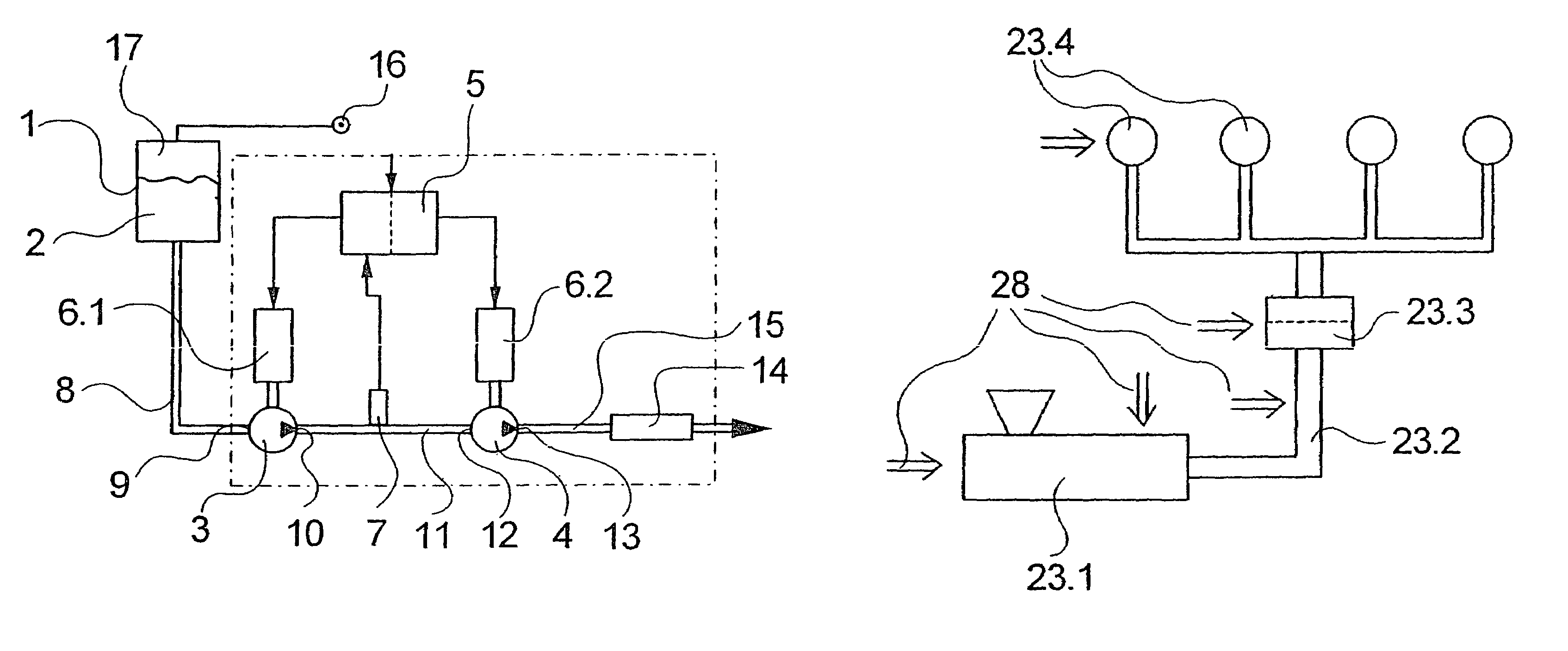
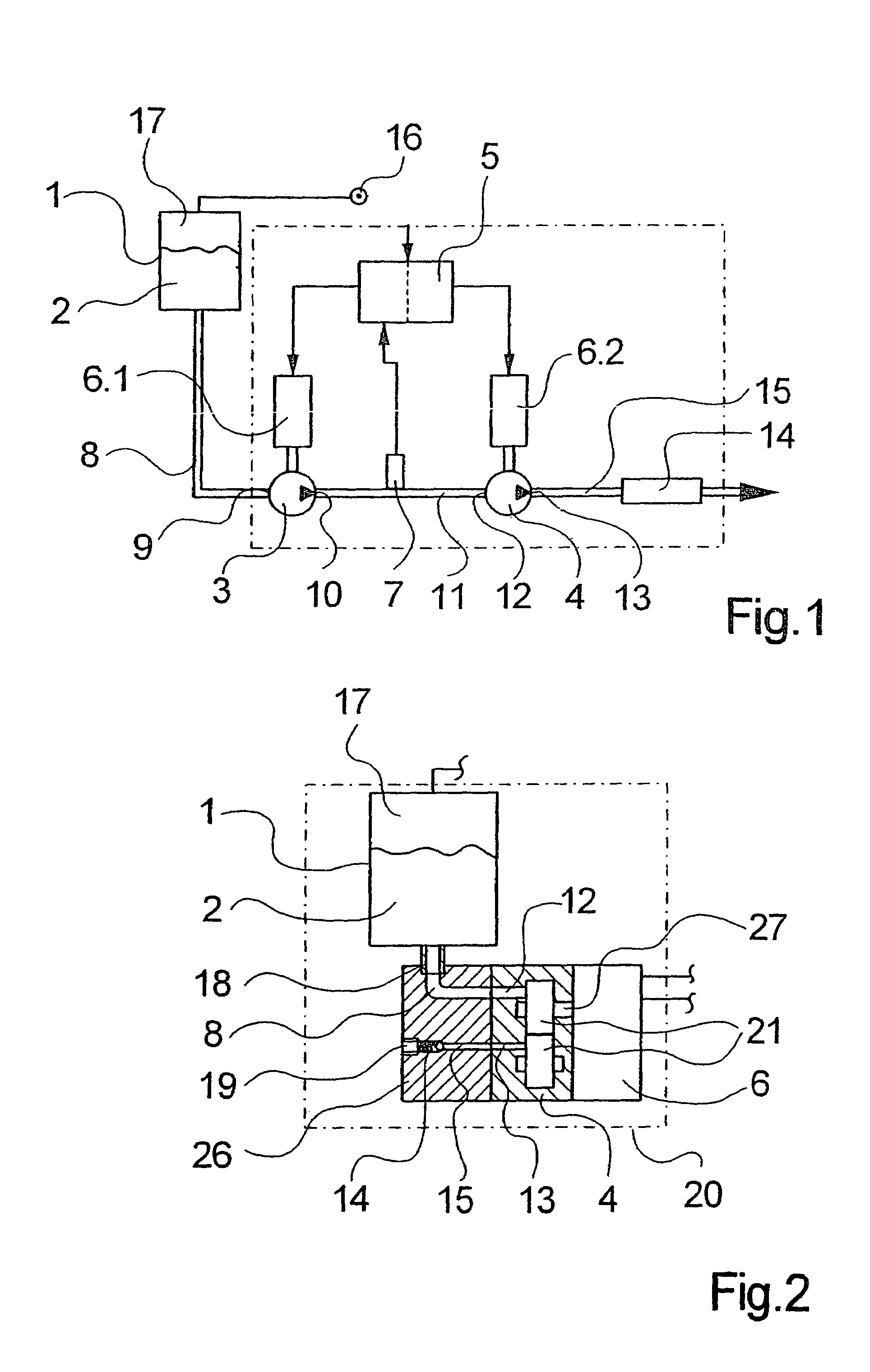
[0028]FIG. 1 illustrates the layout of a first embodiment of the apparatus according to the invention for carrying out the method of the invention.

[0029]The apparatus comprises a feed pump 3 and a metering pump 4. The feed pump 3 connects via a feed inlet 9 and an inlet portion of a dye feed line 8 to a tank 1. The tank 1 contains a liquid dye 2 and may be made heatable. The tank 1 is made airtight and connects on the opposite side of the line 8 to a source of pressure 16. The source of pressure 16 permits a pressure medium, for example, air or nitrogen, to be introduced into a free space above the dye 2 inside the tank 1, so that a gas cushion 17 forms.

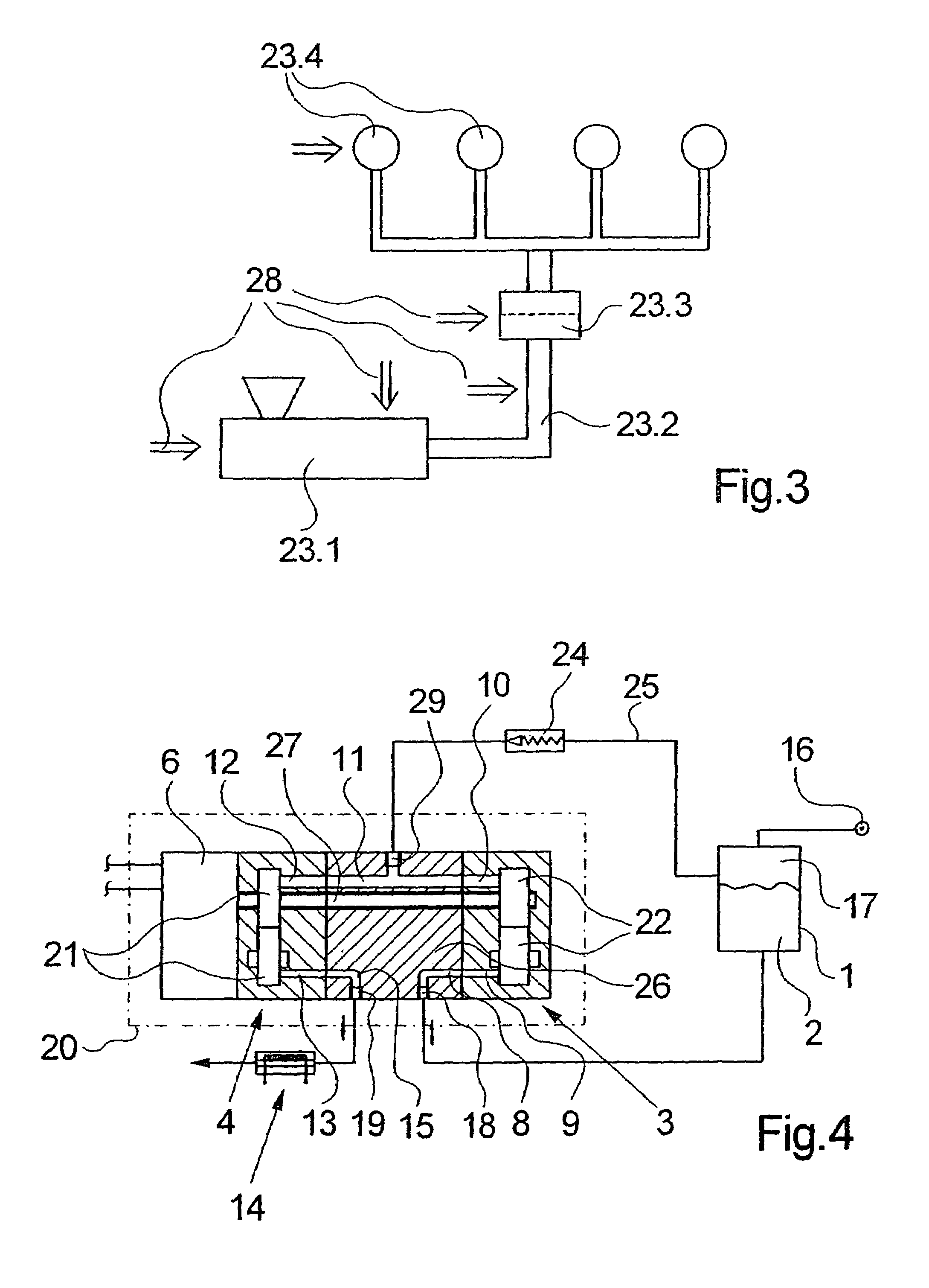
[0030]The feed pump 3 connects via a feed outlet 10 with a downstream portion of the dye feed line 11 to a metering inlet 12 of the metering pump 4. The metering pump 4 connects via a metering outlet 13 and a metering line 15 to a polymer melt carrying component (not shown). The metering line 15 includes a return flow device 14.

[0031...


PUM

PropertyMeasurementUnit
pressureaaaaaaaaaa
constant pressureaaaaaaaaaa
delivery volumeaaaaaaaaaa

Abstract

An apparatus and a method for injecting a liquid dye into a polymer melt, which includes a metering pump with a metering inlet and a metering outlet. The metering inlet connects to a dye tank and the metering outlet connects to a polymer melt carrying component. To add the liquid dye to the polymer melt in the melt carrying component in a quantity that is as uniform and accurate as possible, the invention provides for connecting the metering inlet of the metering pump to a feed outlet of a feed pump, which connects with its feed inlet to the tank. With that, it is possible to generate a feed pressure at the metering inlet of the metering pump, which can be adapted to an injection pressure at the metering outlet of the metering pump.

Description

CROSS REFERENCE TO RELATED APPLICATION[0001]The present application is a continuation of international application PCT / EP2003 / 007435, filed 9 Jul. 2003, and which designates the U.S. The disclosure of the referenced application is incorporated herein by reference.BACKGROUND OF THE INVENTION[0002]The present invention relates to an apparatus for injecting a liquid dye into a polymer melt of the general type disclosed in DE 199 56 251 A1.[0003]To obtain a coloration of the polymer melt when melt spinning synthetic multifilament yarns, it is common practice in the known device to add a liquid dye to the polymer melt and to mix it in a subsequent step. To this end, the dye is stored in a tank. Connected to the tank is a metering pump. The metering pump connects via a line to a spin pump that advances the polymer melt. The spin pump receives the polymer melt via an extruder. To dye the polymer melt, the metering pump adds the liquid dye to the polymer melt in measured quantities.[0004]To...

Claims


Application Information

Patent Timeline
Patent Type & Authority Patents(United States)
IPC IPC(8): B29C45/18B01F15/02B29B7/94B29C48/09B29C48/29B29C48/365B29C48/37B29C48/38D01D1/06F04B13/00F04B23/14F04C11/00F04C13/00F04C14/08
CPCB29B7/94B29C47/364B29C47/1063D01D1/065F04B13/00F04B23/14F04C11/001F04C13/001F04C14/08B29C47/0023B29C47/367B29K2105/0005B29K2105/0032B29K2995/002F04C13/002F04C2220/24F04C2270/18B29C48/29B29C48/09B29C48/37B29C48/387Y10T137/86139B29C48/365D01D1/06
Inventor HELBING, ULRICHSTAUSBERG, GEORGALEXANDER, JORGHASENBURG, JURGEN
Owner SAURER GMBH & CO KG
Why Eureka
Try Eureka