Controller of injection molding machine

a technology of controller and injection molding machine, which is applied in the direction of auxillary shaping apparatus, manufacturing tools, ceramic shaping apparatus, etc., can solve the problems of cumbersome adjustment work or setting work, reduced molding quality, etc., to solve the non-conformity of a reduction tendency and large variation of molded product weigh

Active Publication Date: 2009-04-02
NISSEI PLASTIC IND CO LTD
View PDF7 Cites 34 Cited by
  • Summary
  • Abstract
  • Description
  • Claims
  • Application Information

AI Technical Summary

Benefits of technology

[0009]An object of the present invention is to provide a controller of an injection molding machine that can avoid the effect of a pressure loss based on viscosity of a pressure oil caused by disturbance (temperature change and the like) generated in a hydraulic circuit and its fluctuation and can solve an adverse effect on a molding quality and particularly solve nonconformity of a reduction tendency and a large variation of a molded product weight.
[0010]Another object of the present invention is to provide a controller of an injection molding machine that eliminates a need of adjustment in view of temporal lag or error at detection at a place far from a control target and facilitates the adjustment and setting of a control system with respect to a speed and pressure and can improve accurateness (accuracy) of pressure detection and speed detection.
[0011]Further, another object of the present invention is to provide a controller of an injection molding machine that avoids a problem that an operation at switching becomes instable and largely fluctuates at the switching of a feedback system when a pressure deviation is large and avoids a problem of the occurrence of a rapid drop in the speed so that a stable and more ideal control can be conducted.

Problems solved by technology

However, the above-mentioned conventional injection molding machine (controller) has the following problems to be solved.
By configuring such control system, a physical amount close to the servo motor can be detected and instability in control involved with response delay and the like can be avoided, but since the detection is carried out at a place far from an actual control target, pressure loss based on viscosity by a pressure oil caused by disturbance (temperature change and the like) and its fluctuation generated in a hydraulic circuit in the middle can not be ignored, and particularly, an adverse effect on a molding quality such as a reduction tendency and large variation of a molded product weight is not ignorable.
Therefore, in order to ensure accurateness (accuracy), adjustment or setting of the control system considering such temporal lag or error is needed, and the adjustment work or setting work becomes cumbersome.

Method used


Image

  • Controller of injection molding machine
  • Controller of injection molding machine
  • Controller of injection molding machine

Examples


Embodiment Construction

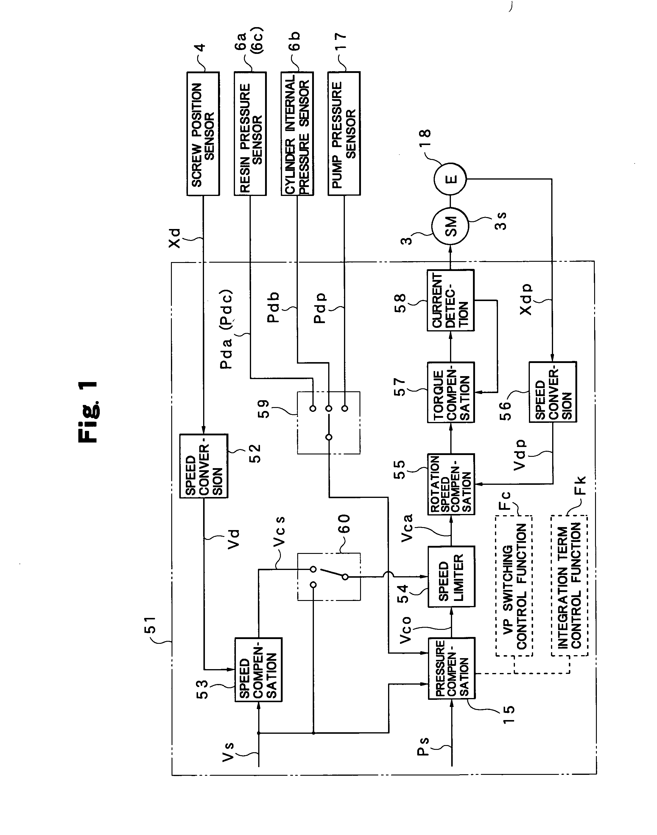
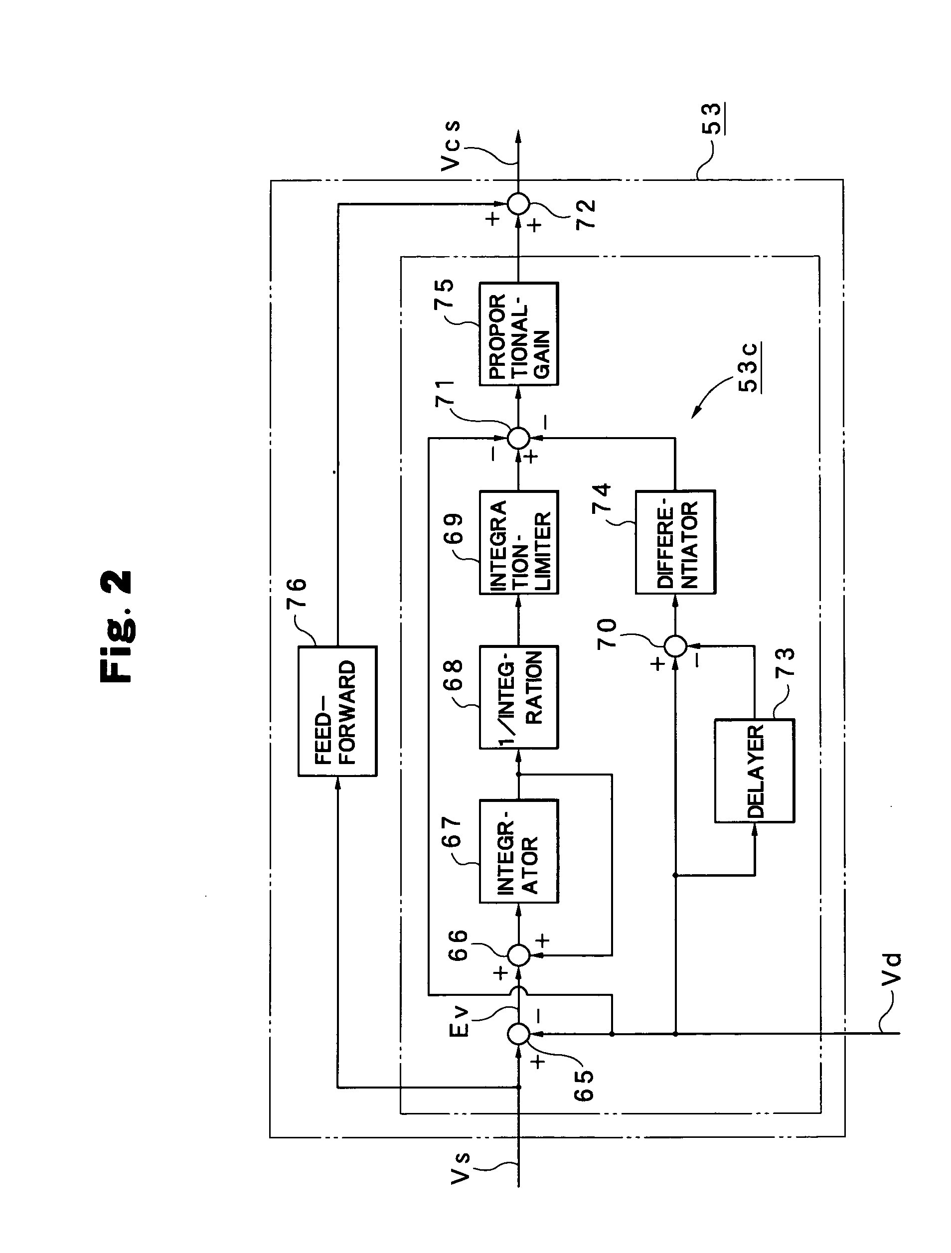
[0025]Next, a preferred embodiment according to the present invention will be described in detail based on the attached drawings. The attached drawings do not specify the invention but are intended to facilitate understanding of the invention. Also, in order to avoid ambiguity of the invention for known portions, detailed description will be omitted.

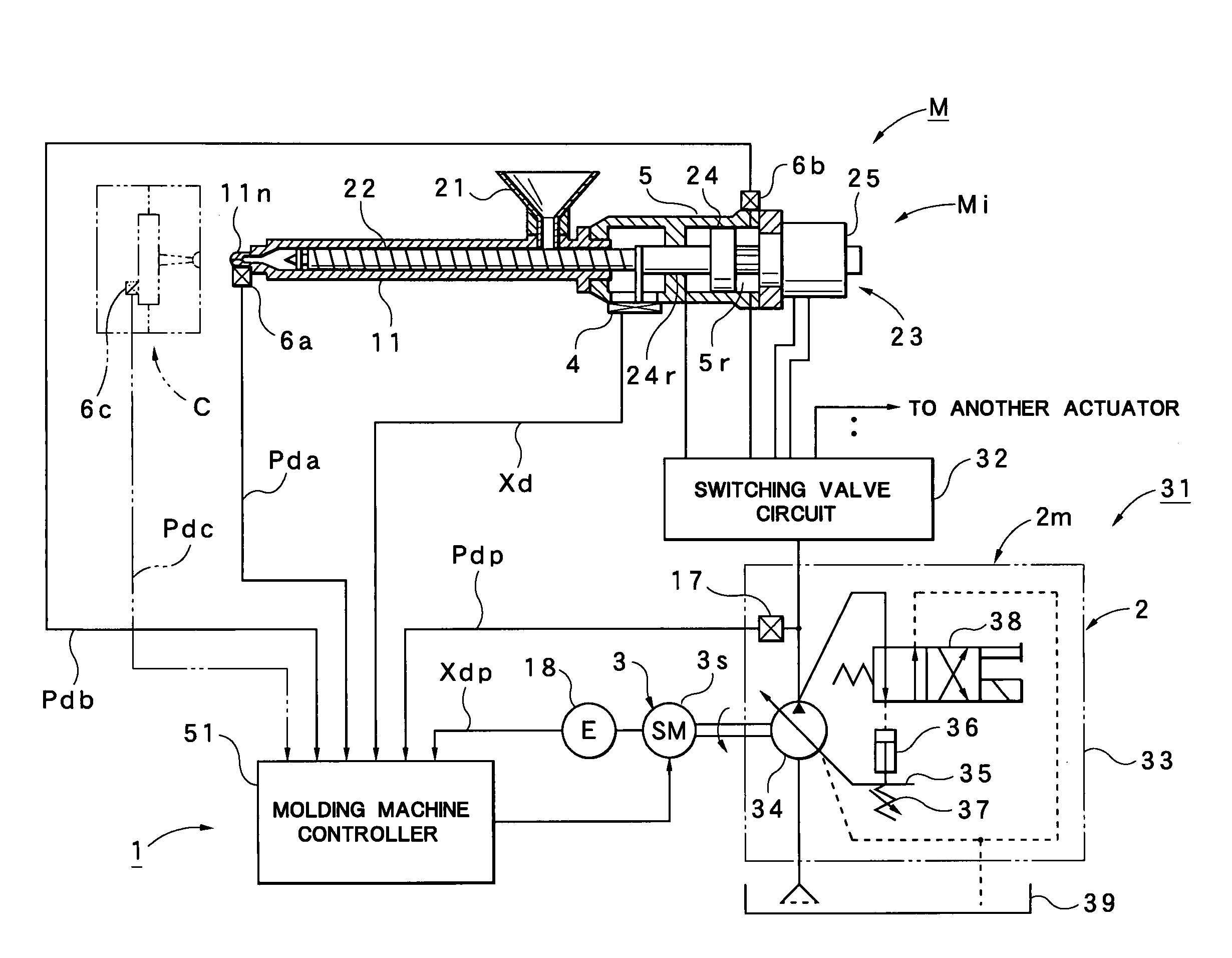
[0026]First, outline configuration of an injection molding machine M provided with a controller 1 according to this embodiment will be described referring to FIG. 4.

[0027]In FIG. 4, reference character M denotes an injection molding machine and is provided with an injection device Mi and a mold clamping device. The mold clamping device is not shown, and only a die C supported by the mold clamping device is shown. The injection device Mi is provided with a heating cylinder 11 having an injection nozzle 11n at a front end and a hopper 21 at a rear end, respectively, a screw 22 is inserted into the heating cylinder 11, and a screw driving p...


PUM

PropertyMeasurementUnit
temperatureaaaaaaaaaa
speedaaaaaaaaaa

Abstract

The present invention comprises a speed feedback control system for carrying out speed feedback control on the basis of a speed detected value Vd obtained by converting a position detected value Xd obtained from a screw position sensor 4, a pressure feedback control system for carrying out a pressure feedback control on the basis of a pressure detected value Pdb obtained from an injection pressure sensor 6b, and a VP switching control function portion Fc for carrying out switching from a speed control region to a pressure control region Zp when a pressure deviation Ep between a preset pressure set value Ps and the pressure detected value Pdb becomes a preset switching determination value Eps or less and carrying out the switching to the pressure control region Zp after control of a speed command value in the speed control region Zv by a predetermined control pattern Dp at this switching.

Description

BACKGROUND OF THE INVENTION[0001]1. Field of the Invention[0002]The present invention relates to a controller of an injection molding machine that controls each operation process in a molding cycle by variably controlling a rotation speed of a driving motor in a hydraulic pump.[0003]2. Description of the Relevant Art[0004]As an injection molding machine on which a controller for controlling each operation process in a molding cycle by variably controlling a rotation speed of a driving motor in a hydraulic pump is mounted, an injection molding machine disclosed in Japanese Patent Laid-Open No. 2007-69500 is known.[0005]This injection molding machine uses a variable discharge type hydraulic pump that can set a fixed discharge flow rate by changing a swash plate angle and is provided with controlling means for controlling each operation process by switching the hydraulic pump to the fixed discharge flow rate corresponding to each operation process set on the basis of a predetermined co...

Claims


Application Information

Patent Timeline
Patent Type & Authority Applications(United States)
IPC IPC(8): B29C45/77
CPCB29C45/77B29C2945/76969B29C2945/76006B29C2945/76083B29C2945/7611B29C2945/76187B29C2945/76214B29C2945/76287B29C2945/76307B29C2945/76381B29C2945/76498B29C2945/76595B29C2945/76665B29C2945/76882B29C2045/776
Inventor HAKODA, TAKASHIKOMAMURA, ISAMUKATO, TOSHIMINAKAMURA, KIYOSHI
Owner NISSEI PLASTIC IND CO LTD
Why Eureka
Try Eureka