Injection Molding Machines and Methods for Accounting for Changes in Material Properties During Injection Molding Runs

a technology of injection molding machine and material properties, which is applied in the direction of auxillary shaping apparatus, manufacturing tools, ceramic shaping apparatus, etc., can solve the problems of non-trivial task, high cost, and limited practical limit of how thin walls of a part may be molded using conventional high variable pressure injection molding process

Active Publication Date: 2015-04-30
IMFLUX INC
View PDF0 Cites 34 Cited by
  • Summary
  • Abstract
  • Description
  • Claims
  • Application Information

AI Technical Summary

Problems solved by technology

Reducing wall thickness using a conventional high variable pressure injection molding process can be an expensive and a non-trivial task.
In fact, conventional injection molding machines (e.g. machines injecting molten plastic resin between about 8,000 psi and about 20,000 psi) have a practical limit as to how thin walls of a part may be molded.
The first is that to achieve very high filling velocities requires very high power loads, and this requires very expensive molding equipment.
Further, most electric presses are unable to provide sufficient power to achieve these high filling rates, or require very complicated and expensive drive systems that substantially increase the cost of the molding equipment making them impractical economically.
The second drawback is that the high filling rates require very high pressures.
These high pressures result in the need for very high clamping forces to hold the mold closed during filling, and these high clamping forces result in very expensive molding equipment.
These high strength molds are also very expensive, and can be impractical economically for many molded components.
Further, some molded components require very thin design elements to perform properly, such as design elements that need to flex, or design elements that must mate with very small features of other design elements.
As material freezes, it also shrinks, pulling away from the mold cavity walls, which reduces effective cooling of the material by the mold cavity walls.
Increasing the pressure, however, has both cost and performance downsides.
As the pressure required to mold the component increases, the molding equipment must be strong enough to withstand the additional pressure, which generally equates to being more expensive.
Thus, a decrease in the wall thickness of a given part can result in significant capital expenses to accomplish the manufacturing via conventional inject

Method used


Image

  • Injection Molding Machines and Methods for Accounting for Changes in Material Properties During Injection Molding Runs
  • Injection Molding Machines and Methods for Accounting for Changes in Material Properties During Injection Molding Runs
  • Injection Molding Machines and Methods for Accounting for Changes in Material Properties During Injection Molding Runs

Examples


Embodiment Construction

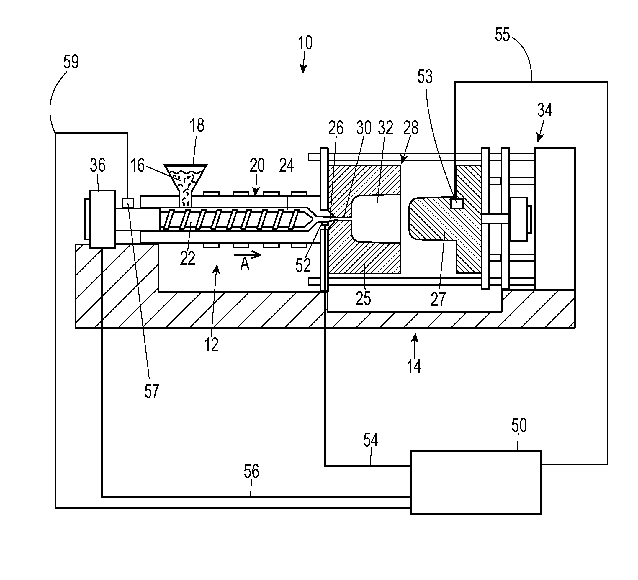
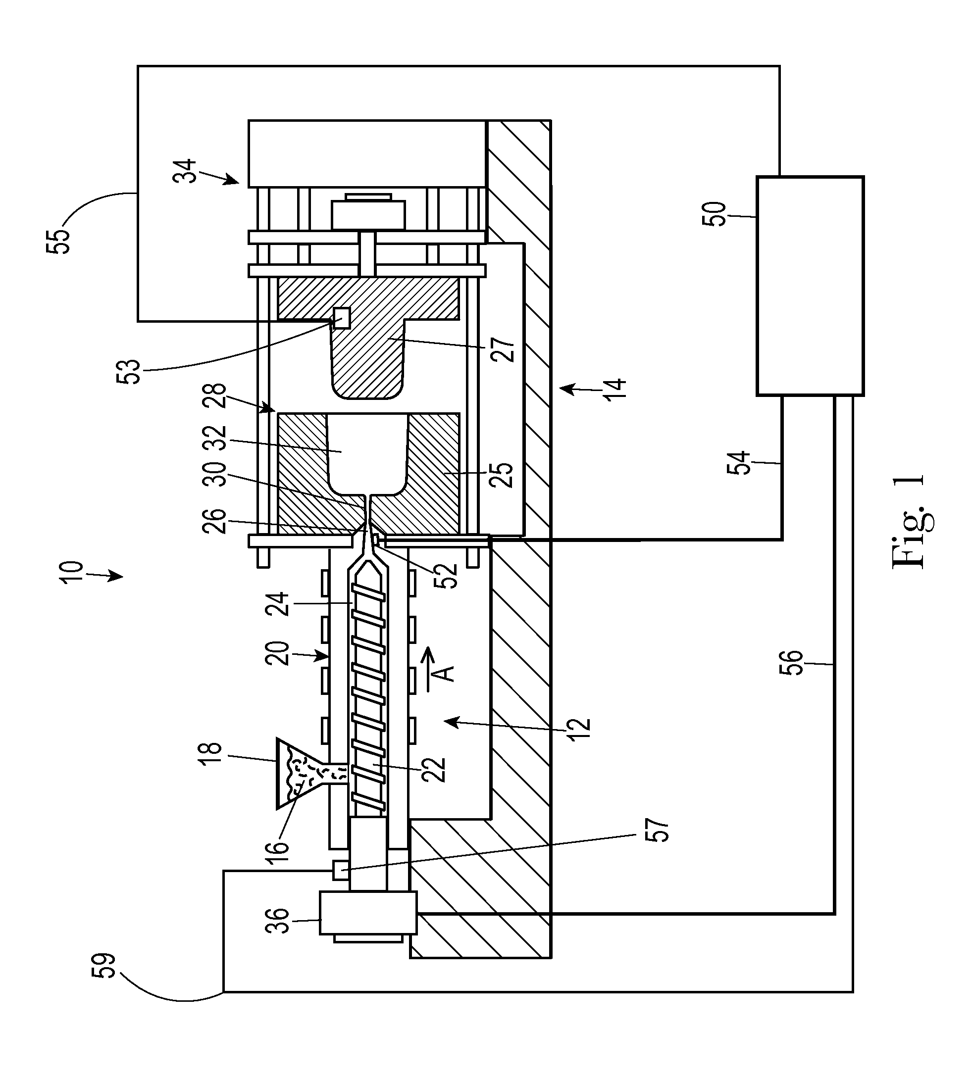
[0027]Embodiments of the present invention generally relate to systems, machines, products, and methods of producing products by injection molding and more specifically to systems, products, and methods of producing products by low substantially constant pressure injection molding. However, the devices and methods for accounting for viscosity changes in the molten plastic material described herein are not limited to low substantially constant pressure injection molding machines and processes. Rather, the disclosed devices and methods for accounting for viscosity changes in the molten plastic material may be incorporated into virtually any injection molding machine or process, including, but not limited to, high pressure processes, low pressure processes, variable pressure processes, and constant or substantially constant pressure processes.

[0028]The term “low pressure” as used herein with respect to melt pressure of a thermoplastic material, means melt pressures in a vicinity of a n...


PUM

PropertyMeasurementUnit
Fractionaaaaaaaaaa
Timeaaaaaaaaaa
Timeaaaaaaaaaa

Abstract

A method and a machine account for changes in material properties of molten plastic material during an injection run. A change in a control signal is calculated by a controller during the injection molding run. If the change in the control signal indicates a change in material flowability, the controller alters a target injection pressure to ensure that molten plastic material completely fills and packs a mold cavity to prevent part flaws such as short shots or flashing.

Description

TECHNICAL FIELD OF THE INVENTION[0001]The present invention relates to injection molding machines and methods of producing injection molded parts and, more particularly, to injection molding machines that adjust operating parameters of the injection molding machine during an injection molding run to account for changes in material properties of the injection material and methods of accounting for changes in injection molding material properties during an injection molding run.BACKGROUND OF THE INVENTION[0002]Injection molding is a technology commonly used for high-volume manufacturing of parts made of meltable material, most commonly of parts made of thermoplastic polymers. During a repetitive injection molding process, a plastic resin, most often in the form of small beads or pellets, is introduced to an injection molding machine that melts the resin beads under heat, pressure, and shear. The now molten resin is forcefully injected into a mold cavity having a particular cavity shap...

Claims


Application Information

Patent Timeline
IPC IPC(8): B29C45/77B29C45/00
CPCB29C45/77B29C45/0025B29C2945/76076B29C2945/76257B29C2945/76545B29C2945/76859B29C2945/7621B29C2945/76381B29C45/7646B29C2945/7601B29C2945/76933B29C2945/76936
Inventor ALTONEN, GENE MICHAELMCCONNELL, KIMBERLY NICHOLEBREIDENBACH, VINCENT SEANGERGOV, MILKO GEORGIEV
Owner IMFLUX INC
Why Eureka
Try Eureka