Method of and system for fluid purification

a technology of fluid purification and fluid injection, applied in the direction of multi-stage water/sewage treatment, evaporator regulation/control, separation process, etc., can solve the problems of affecting the efficiency of lubricating oil, and affecting the performance of lubricating oil

Inactive Publication Date: 2004-07-22
OIL PURIFICATION SYST
View PDF58 Cites 17 Cited by
  • Summary
  • Abstract
  • Description
  • Claims
  • Application Information

AI Technical Summary

Problems solved by technology

Over time, particulates and liquid contaminants such as water, antifreeze, and fuel degrade the performance of lubricating oil.
Currently, contaminated oil is changed at regular intervals because the liquid contaminants and small particulates are not easily filtered out of the lubricating oil.
However, the single canister design tends to be bulky, problematic to install, and more expensive to service.
The flow of oil is impeded by ridges along the exterior of the cup and therefore more evaporation may occur.

Method used


Image

  • Method of and system for fluid purification
  • Method of and system for fluid purification
  • Method of and system for fluid purification

Examples


Embodiment Construction

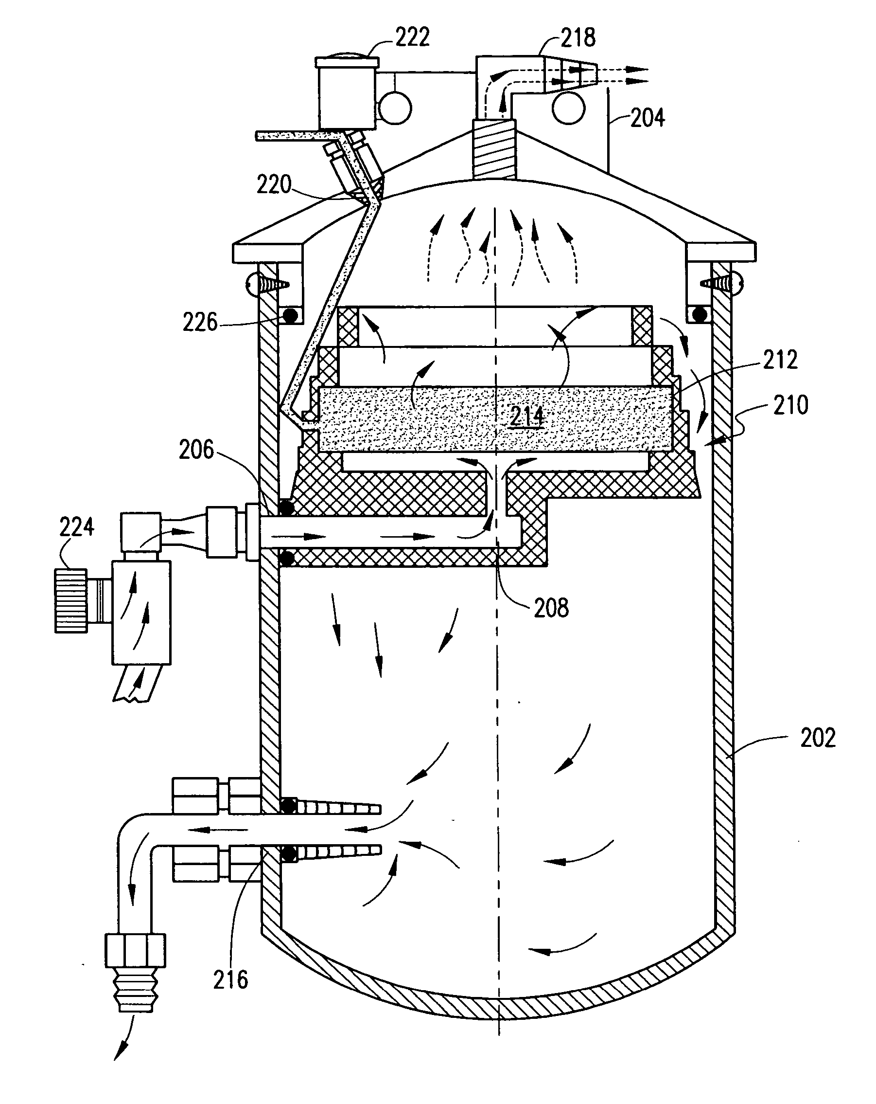
[0022] A two canister fluid purification system provides several advantages for the effective purification of lubricating and hydraulic fluids. For example, by separating the filtration canister from the evaporation canister, a metering valve may be placed between the filtration canister and evaporation canister, thereby allowing proper control of the flow of fluid, such as oil or hydraulic fluid, to and from both canisters. In addition, the two canisters need not be located adjacent each other and therefore, the canisters may be installed in various locations to provide flexibility to the installer. It has been found that the evaporation canister should be placed in a location substantially above the engine so that gravity may assist the fluid in returning from the evaporation canister to the engine. However, the filtration canister may be located anywhere within the engine compartment, due to the fact that the filtration canister is under pressure.

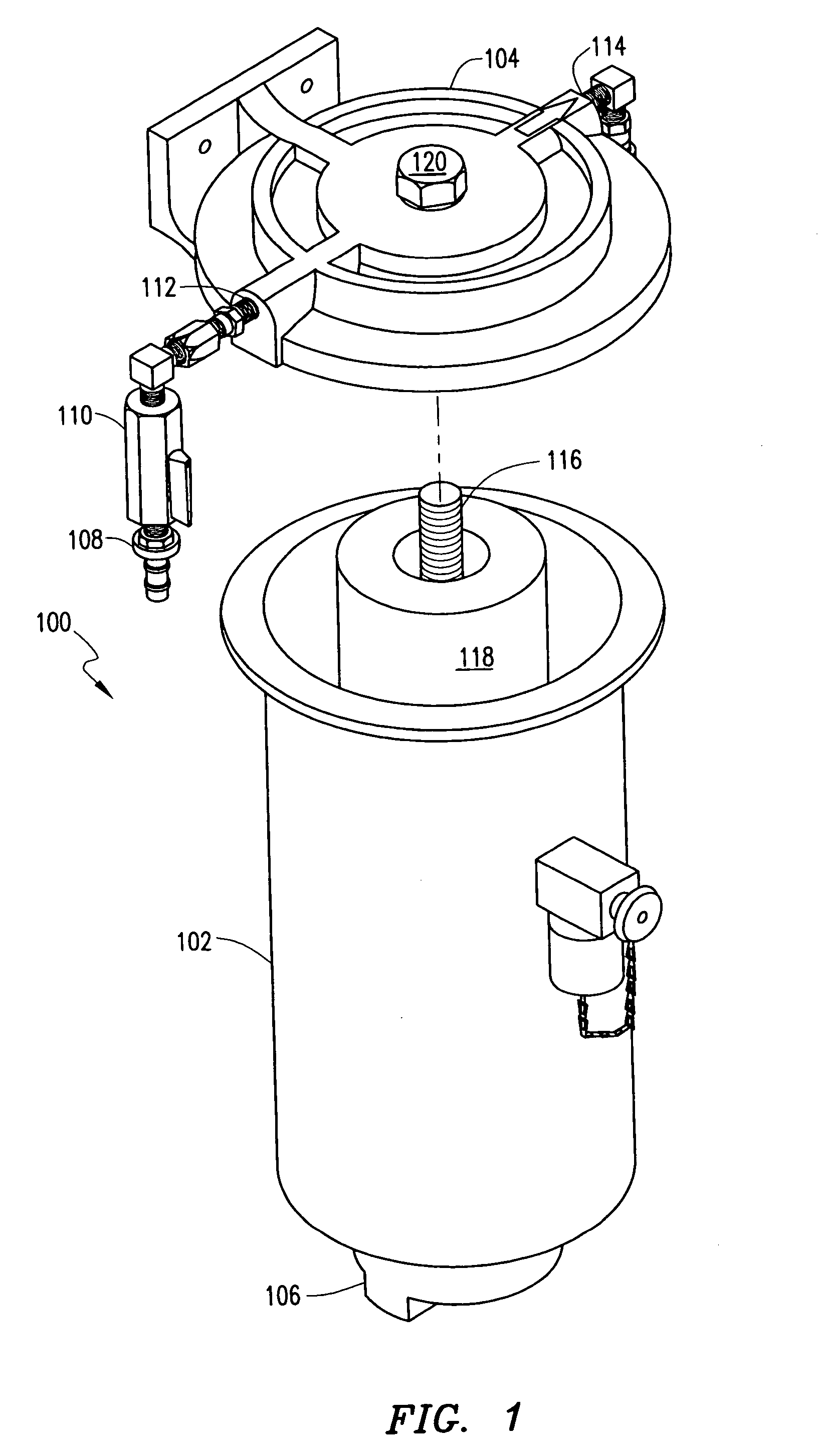
[0023] Referring now to FIG. 1, a...


PUM

PropertyMeasurementUnit
temperatureaaaaaaaaaa
electrical poweraaaaaaaaaa
pressureaaaaaaaaaa

Abstract

A method of and system for purifying fluid of an internal combustion engine or hydraulic system utilizes an evaporation chamber separate from a filtering chamber. A metering valve may be oriented between the filtering chamber and the evaporation chamber to control the flow of fluid to the evaporation chamber.

Description

[0001] This patent application claims priority to, and incorporates by reference the entire disclosure of, co-pending U.S. Provisional Patent Application No. 60 / 426,712, which was filed on Nov. 15, 2002.[0002] 1. Technical Field of the Invention[0003] The present invention is generally related to fluid purification, and more specifically, but not by way of limitation, to a system and method for fluid purification by utilizing separate evaporation and filtration chambers particularly adapted for purification of lubricating, hydraulic, and other oils.[0004] 2. Description of Related Art[0005] Internal combustion engines and hydraulic systems typically utilize oil to lubricate the moving parts included therein. Over time, particulates and liquid contaminants such as water, antifreeze, and fuel degrade the performance of lubricating oil. Currently, contaminated oil is changed at regular intervals because the liquid contaminants and small particulates are not easily filtered out of the l...

Claims


Application Information

Patent Timeline
Patent Type & Authority Applications(United States)
IPC IPC(8): B01B1/00B01D1/00B01D29/00B01D35/00B01J
CPCB01B1/005B01D29/00B01D1/0082
Inventor WHITMORE, C. BARCLAYGUTIERREZ, JAVIER G.GUTIERREZ, JOSE G.
Owner OIL PURIFICATION SYST
Why Eureka
Try Eureka