Eureka AIR delivers breakthrough ideas for toughest innovation challenges, trusted by R&D personnel around the world.

Microfluidic system for the manipulation and concentration of particles suspended in liquid

Inactive Publication Date: 2004-07-29
CSEM CENT SUISSE DELECTRONIQUE & DE MICROTECHNIQUE SA RECH & DEV
View PDF0 Cites 6 Cited by
  • Summary
  • Abstract
  • Description
  • Claims
  • Application Information

AI Technical Summary

Problems solved by technology

Such methods do not allow one to remove or otherwise manipulate the beads after they have been positioned.
Furthermore, they are limited to beads above a certain size, typically several micrometers.

Method used


Image

  • Microfluidic system for the manipulation and concentration of particles suspended in liquid
  • Microfluidic system for the manipulation and concentration of particles suspended in liquid
  • Microfluidic system for the manipulation and concentration of particles suspended in liquid

Examples


Embodiment Construction

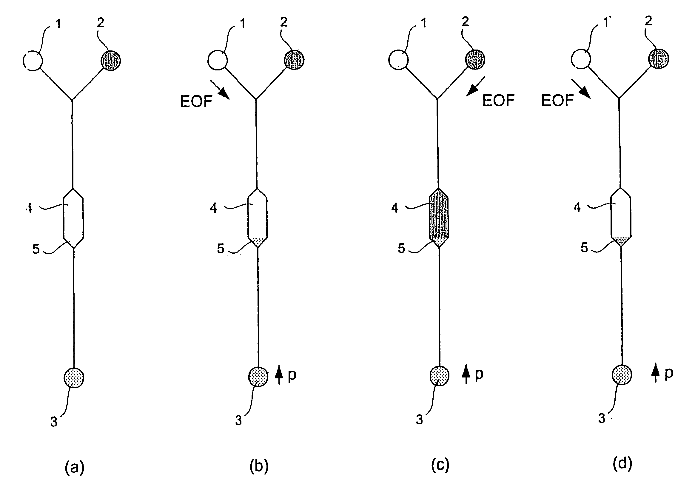
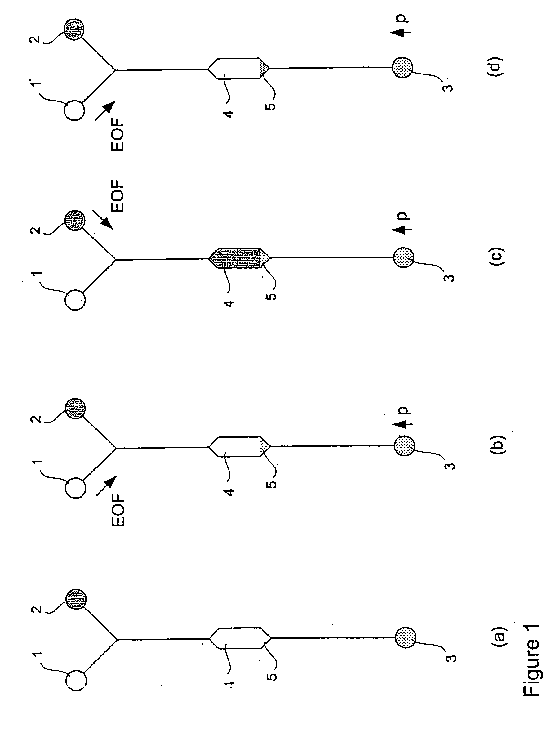
[0004] FIG. 1 illustrates an embodiment of apparatus used and steps performed in a preferred embodiment of the invention and particularly shows how an immunoreaction is performed. From this embodiment, it is easy for any one skilled in the art to devise more elaborate immunoassay formats well known in the state of the art, for example competitive assay formats or sandwich assay formats, and to devise more complex automated apparatus.

[0005] FIG. 1(a):

[0006] The system consists of a reservoir 1 containing a buffer solution, a reservoir 2 containing fluorescently marked molecules, and a reservoir 3 containing functionalised beads in a buffer solution. The reservoirs are connected via capillaries. An expanded section 4 is present in the capillaries with a flared area 5 where vortices are formed under pressure / EOF (electro-osmotic flow) counterflow conditions. In order to add or remove beads from the device, the reservoirs may be filled with suitable solutions or suspensions of beads. Wi...


PUM


Abstract

A microfluidic system for the concentration of particulate matter comprises a first reservoir (1) containing a buffer solution, a second reservoir (2) containing a analyte, and a third reservoir (3) containing beads suspended in a liquid. Microchannels link the reservoirs and an expanded portion (4). Hydrostatic pressure is applied to the reservoir (3) containing the beads while an electro-osmotic force (EOF) is applied between the reservoir (1) and the reservoir (3) to establish counter flows of liquids. A vortex forms in the flared portion (5) due to the counter flow of the liquids and the beads are concentrated in the vortex. By switching the EOF between reservoirs (1) and (2) the buffer solution can be replaced by the analyte to enable an analysis to be performed.

Description

[0001] The present invention relates to a microfluidic system for the concentration of particulate matter and may be applied to a microfluidic system capable of accumulating and retaining large molecules or small beads in specific locations on a chip and perfusing them with liquids containing analytes, analyte / marker combinations, washing buffers etc. To achieve this, the invention provides a method and apparatus for locating particles in a vortex formed under pressure / electro-osmotic counterflow conditions.[0002] The invention may be used, for example, for immunoassay or nucleic acid hybridisation based bioanalysis. In a preferred aspect of the invention opposing electro-osmotic and pressure driven flows are established in one or more capillaries such that liquid is flowing in one direction close to the walls and in the other direction at the centre of the capillaries. The capillaries have expanded sections at locations where the cross-sections increase. As a result, vortices are e...

Claims


Application Information

Patent Timeline
IPC IPC(8): B01L3/00
CPCB01L3/5027B01L2400/0487B01L2400/0418B01L2200/0668
Inventor BOER, GERBENDODGE, ARASHLETTIERI, GIANLUCAVERPOORTE, ELISABETH
Owner CSEM CENT SUISSE DELECTRONIQUE & DE MICROTECHNIQUE SA RECH & DEV
Why Eureka
Eureka Blog
Learn More