
Air distribution device

Inactive Publication Date: 2004-07-29
AIR INNOVATION SWEDEN
View PDF7 Cites 2 Cited by
  • Summary
  • Abstract
  • Description
  • Claims
  • Application Information

AI Technical Summary

Benefits of technology

[0005] Furthermore, the object is to enable a unique treatment of air in such a ventilating device in order to additionally increase the air quality in this primary part of the air volume by aftertreating the air before it is let out in the primary near zone.
[0006] Furthermore, the object is to obtain satisfactory ventilation at a working place with large cost savings in comparison with conventional ventilation plants.
[0013] Furthermore, the device may be provided with one or more detachable supplementary modules, which are placed in a fastener adapted for the module in the device. The supplementary modules are provided with a radiator, a cooling coil, a moistening element, an ionization element, a filter element, a scent element or a combination of one or more of these elements with the purpose of influencing the fresh air flowing through the modules. It is thereby possible to manually bypass one or more modules by easily accessed control members. Filter units are placed either at the inlet opening before the pump or as a supplementary module or as a separate filter at an outlet opening. Also combinations of these filter arrangements are feasible.

Problems solved by technology

Naturally, it is associated with large costs to dimension and install as well as operate a large ventilation plant in comparison with a small plant.
An additional cost implication is also temperature factors, cooling factors, filtering, ionization factors and moisture on the supply air, which all factors drastically increase the costs at large plants in comparison with small plants.

Method used


Image

  • Air distribution device
  • Air distribution device

Examples


Embodiment Construction

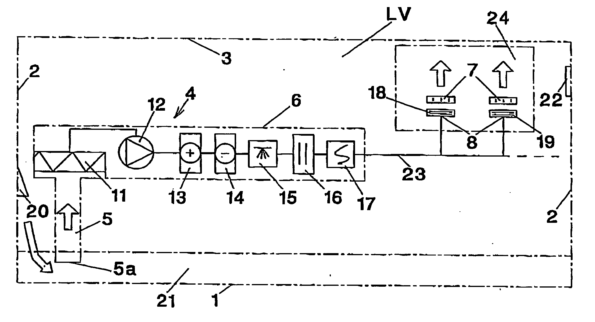
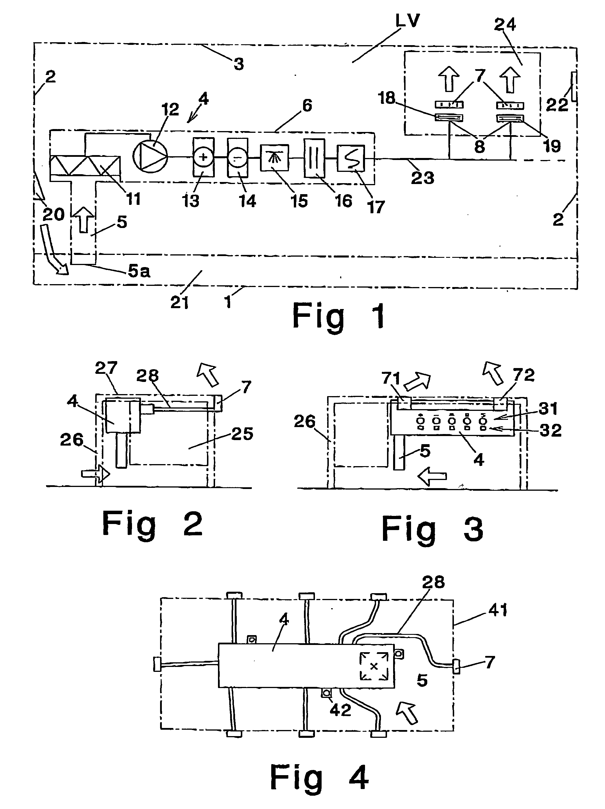
[0020] In an air volume LV that is limited by a floor 1, walls 2 and a ceiling 3, a distribution device 4 is mounted. The device consists of an inlet unit 5 having an inlet opening 5a. Furthermore, in the direction of flow the device consists of a main unit 6 including a main filter 11 in class F=8-11, a pump 12 as well as a number of supplementary modules 13, 14, 15, 16, 17. It should be emphasized that also the main filter 11 may be formed as a supplementary module. A first supplementary module 13 is provided with a radiator intended to heat the fresh air flowing through the module. A second supplementary module 14 is provided with a cooling coil intended to cool the fresh air flowing through the module. The heating and cooling capacity, respectively, for these modules is .+-.5-8.degree. C. from the supply air temperature in question. A third supplementary module 15 comprises a moistening element intended to moisten the fresh air flowing through the module with up to 3 g / kg. A fou...


PUM


Abstract

Air distribution device (4) provided with an inlet opening (5a) and at least one outlet opening (8) for conveyance of air from a fresh air area (21) to at least one ventilation area (24) in an air volume (LV) limited by floor (1), walls (2) and ceiling (3), said fresh air area (21) being situated along the floor in the air volume (LV), the distribution device (4) being arranged to locally supply fresh air from the fresh air area (21) to a near zone of the respiratory organ of an individual in the air volume (LV).

Description

[0001] The present invention relates to a distribution unit as a complement to a supply air terminal unit through which fresh air is supplied to a room volume.[0002] Existing supply air terminal units are formed to provide an air volume with fresh air by being dimensioned to exchange the entire air of the air volume during a determined period of time. Thus, larger supply air terminal units and larger ventilation plants are required for large air volumes than for small air volumes. Naturally, it is associated with large costs to dimension and install as well as operate a large ventilation plant in comparison with a small plant. An additional cost implication is also temperature factors, cooling factors, filtering, ionization factors and moisture on the supply air, which all factors drastically increase the costs at large plants in comparison with small plants. Furthermore, conventional supply air terminal units are intended to enable ventilation of an air volume so that the fresh air...

Claims


Application Information

Patent Timeline
IPC IPC(8): F24F3/12F24F13/06
CPCF24F3/12F24F2221/38F24F13/06
Inventor NYSTROM, BERNT
Owner AIR INNOVATION SWEDEN
Learn More