Flap-equipped interlabial pad

Inactive Publication Date: 2004-08-12
UNI CHARM CORP
View PDF7 Cites 71 Cited by
  • Summary
  • Abstract
  • Description
  • Claims
  • Application Information

AI Technical Summary

Problems solved by technology

However, since the sanitary napkin, used by being fixed to clothes, has. intrinsically poor adhesion near the ostium vaginae, position shift may occur between the underwear to which the sanitary napkin is fixed and the inner thigh due to the body action of the wearer, and an unnecessary gap generates sometimes.
If it absorbs a large amount of menstrual blood, the fixing position may be displaced due to its own weight, and in the worst cases, it may fall off from the inside of the labia.
In this case, the function to fit the interlabial pad to body does not work sufficiently, and even menstrual blood leaks.
However, when comparatively large amount of body fluid is discharged, it is highly likely that the body fluid enter the bonding interface where the adhesive and the inner surface of the labia touch to each other.
Especially, in the case that urine is discharged all at once from the urinary duct such as abdominal pressure urinary incontinence, the incontinence pad is likely to fall off from the labia due to the momentum of the urine gushed out.
In this

Method used


Image

  • Flap-equipped interlabial pad
  • Flap-equipped interlabial pad
  • Flap-equipped interlabial pad

Examples


first embodiment

[0119]

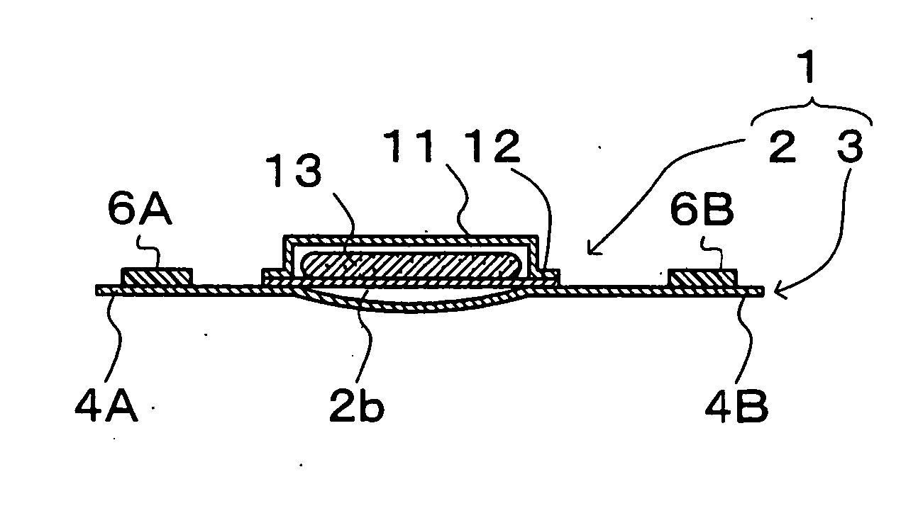
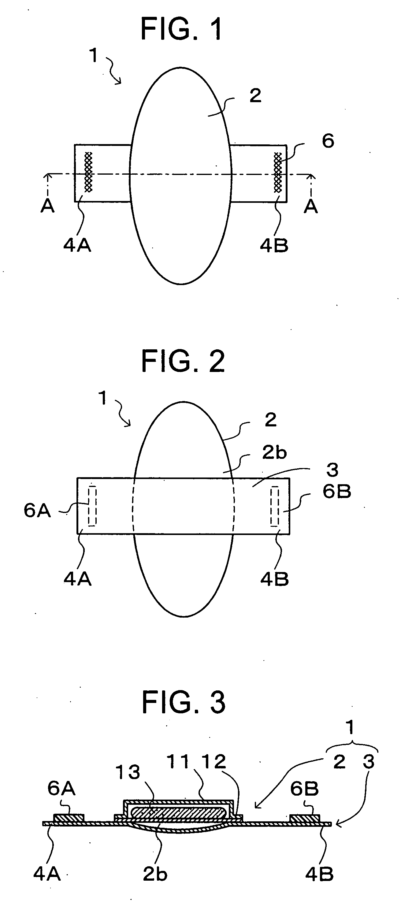
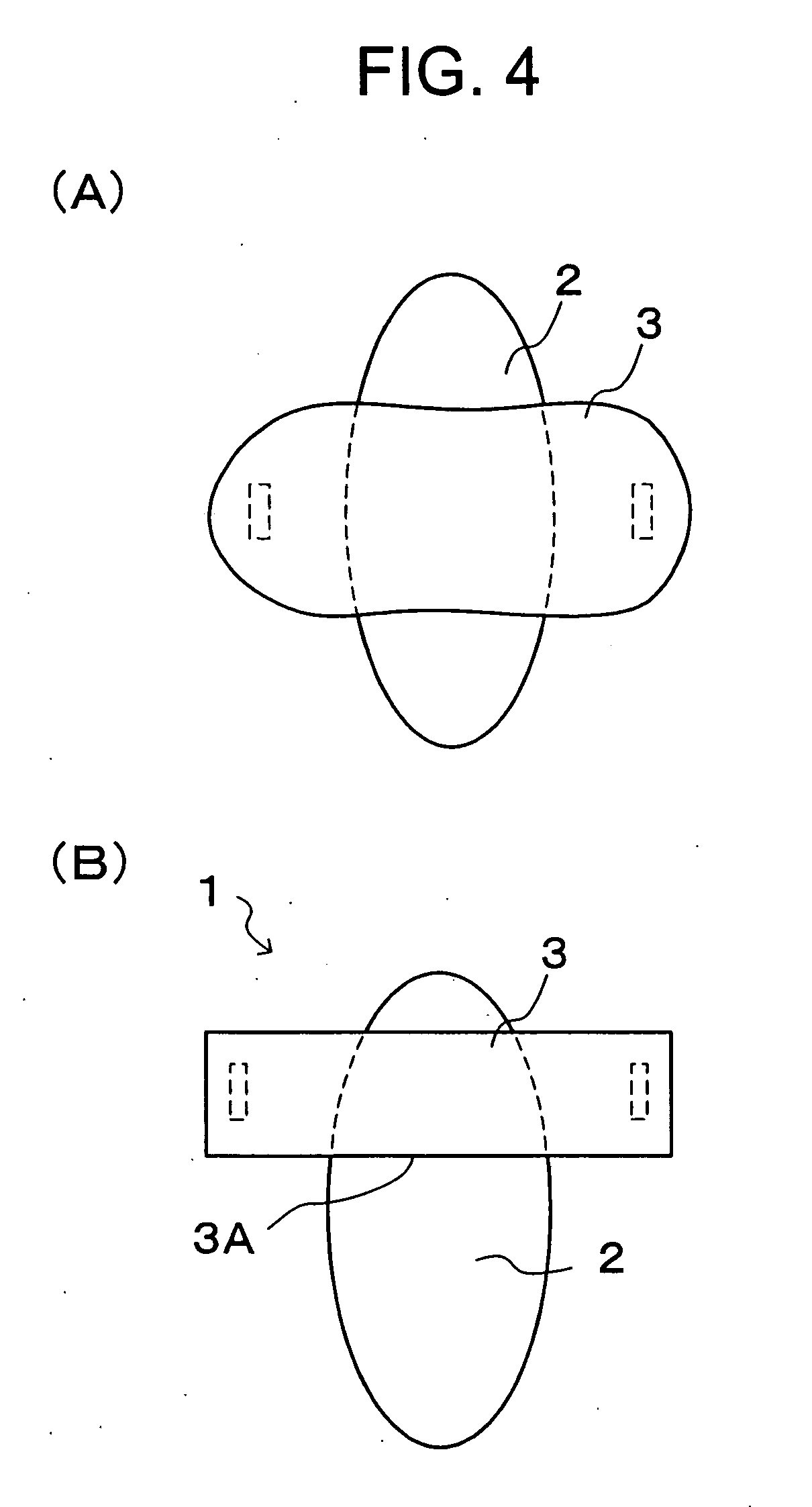
[0120] FIG. 1 is a simplified perspective view showing the body side face of the interlabial pad with of the flap portions according to the first embodiment. FIG. 2 is a simplified perspective View showing the opposite side to the body side of the interlabial pad with of the flap portions according to the first embodiment. FIG. 3 is a cross section A-A in FIG. 1. FIG. 4 is a view showing another configuration of the interlabial pad with the flap portions.

[0121] As shown in FIG. 1, the interlabial pad 2 has the lateral dimension and the longitudinal dimension, the latter being substantially longer than the former. And as shown in FIG. 2, the mini-sheet piece 3 having a lateral dimension that is larger than that of the interlabial pad 2 is attached to the opposite side face to the body side face 2b of the interlabial pad 2 in such a way that a part of the mini-sheet piece 3 protrudes from the both side edges of the interlabial pad 2 with heat seal or an adhesive. The protruded ...

second embodiment

[0135]

[0136] The interlabial pad with the flap portions of the second embodiment will now be explained.

[0137] FIG. 9 is a view showing the body side face of the interlabial pad with the flap portions 20 of the second embodiment. FIG. 10 is a view showing the opposite side face to the body side face of the interlabial pad with the flap portions 20. FIG. 11 is a perspective view of the interlabial pad with the flap portions 20. FIG. 12 is a cross section C-C of FIG. 9.

[0138] As shown in FIG. 9, the interlabial pad with the flap portions 20 of this embodiment comprises the interlabial pad 22, the flap portions 24A and 24B at both sides of the interlabial pad 22 and the long convex area 21 on the body side face 22a of the interlabial pad 22. In addition, as shown in FIG. 10, the interlabial pad with the flap portions 20 of this embodiment also comprises the mini-sheet piece 23 on the opposite side face to the body side face 22b of the interlabial pad 22. The finger insertion opening 23...


PUM

PropertyMeasurementUnit
Forceaaaaaaaaaa
Forceaaaaaaaaaa
Lengthaaaaaaaaaa

Abstract

The present invention relates an interlabial pad to be fitted to the labia providing an interlabial pad with flap portions that can maintain the retention state in the interlabial space irrespective of the quantity of body fluid discharge such as menstrual blood. A mini-sheet piece (3) is attached to the opposite side face to the body side face (2b) of the interlabial pad (2) in such a way that a part of it protrudes from both side edges of the interlabial pad (2) forming flap portions (4A) and (4B). Adhesives (6A) and (6B) are applied to the body side face of the flap portions (4A) and (4B). The interlabial pad (2) is retained in the interlabial space and the flap portions (4A) and (4B) are affixed to the surface of the labia majora to fit the interlabial pad with the flap portions (1).

Description

[0001] This application is a Continuation of International Application No. PCT / JP02 / 04896 filed May 21, 2002, which application published in Japanese on Nov. 28, 2002 as WO 02 / 094160 A1 under PCT Article 21(2).[0002] 1. Technical Field[0003] The present invention relates to an interlabial pad fitted on female's labia[0004] 2. Background Art[0005] Conventionally, sheet type absorbent products like a sanitary napkin are used generally as female sanitary products to absorb body fluid such as menstrual blood. Here, there have been great efforts to prevent the leak of menstrual blood from a gap caused by poor adhesion near the ostium vaginae as for the sanitary napkin.[0006] However, since the sanitary napkin, used by being fixed to clothes, has. intrinsically poor adhesion near the ostium vaginae, position shift may occur between the underwear to which the sanitary napkin is fixed and the inner thigh due to the body action of the wearer, and an unnecessary gap generates sometimes.[0007]...

Claims


Application Information

Patent Timeline
IPC IPC(8): A61F13/15A61F13/82A61F15/00B65D85/07
CPCA61F13/15252A61F13/4702A61F13/4704A61F13/47209A61F13/476A61F13/505A61F2013/8497A61F2013/15235A61F2013/15357A61F2013/4729A61F2013/53445A61F2013/8402A61F13/55165
Inventor MIZUTANI, SATOSHIYAMAKI, KOICHINODA, YUKITOKUMOTO, MEGUMISAKAI, AKANE
Owner UNI CHARM CORP
Why Eureka
Try Eureka